 Jeff Cooper
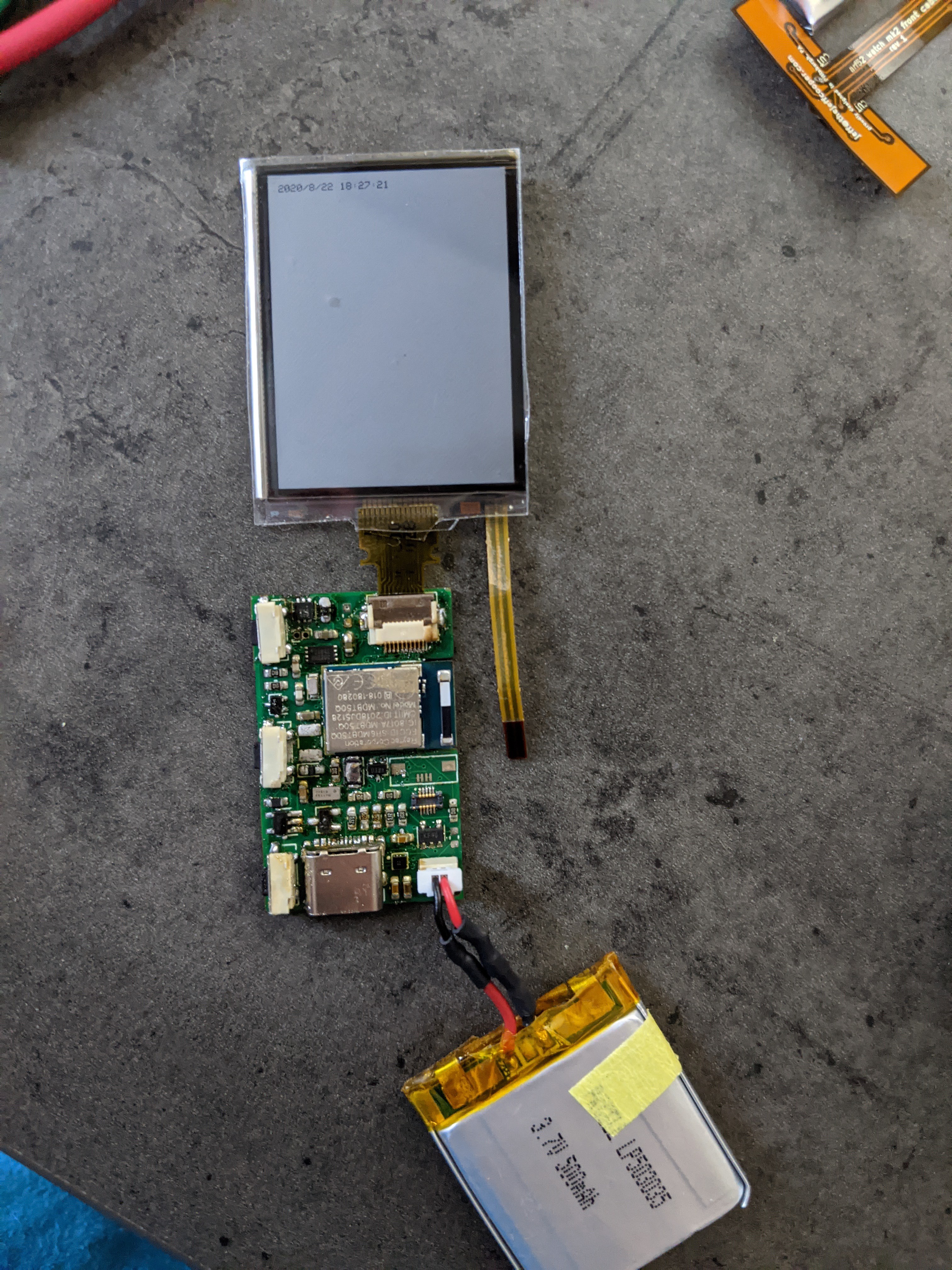
This is an exciting milestone: I have a portable device that can keep track of time! I've finished soldering all of the components on the board (except the header for the LCD backlight), and it all seems to work. The only problem is the MAX17220 stubbornly refuses to cooperate: after letting the magic smoke out of a few, I finally replaced some of the components that JLC soldered on and got it "working"... but it doesn't actually boost to 5V like it should. Instead, it seems to buck USB to about 3.4V, and do nothing to the 2.8V input voltage. I've replaced and reseated the component enough times to be decently confident that it isn't an assembly problem. I actually replaced the one on the board in this picture with a fresh one after taking this picture... and it smoked as soon as I plugged it in. HOWEVER: the display still worked at 2.8V, it just had a nasty flicker when it updated. The display's datasheet says it can handle a maximum voltage of 5.8V, which is safely above the maximum 5.25 for in-spec USB... so I made a solder bridge between VIN and 5V, and the screen works great! The next revision will just not bother with a 5V booster, and I'll just run the display a little out of spec. Yay for simplicity!
Otherwise, the buttons (mounted on the left side of the PCB in this picture) and the flashlight (attached to the flexible PCB at the top right of the picture) work fine. There's a small risk of something overheating, but the flashlight LED (Cree XM-L2) is brighter than the one on my cell phone, which I'm very pleased with. I'm getting data from the MAX17262 fuel gauge IC, but I haven't yet gone through any sort of calibration or setup. I haven't tested the flash memory, but seeing as it's on the SPI bus with the screen I'm not immensely worried.
I do think I'm going to need to come up with a better solution for the battery, though. even the tiny JST-SH connector is huge compared to the rest of the board, and the heatshrink-protected cables aren't flexible enough to assemble the whole thing in its case. Now that I'm reasonably confident that I'm not going to set anything on fire, I'm probably just going to leave holes to solder battery leads in to.
My next priority is to get rev3 of the board built and sent to the fab; I expect it to look an awful lot like rev2. I will probably move some low-profile passives to the bottom of the board, though, so that I can switch back to a 2-layer board. The faster turn time seems worth it to me.
Discussions
Become a Hackaday.io Member
Create an account to leave a comment. Already have an account? Log In.