José Júnior
Things I shoved on the board so far:
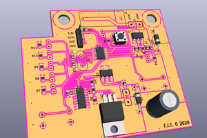
32 Pin connector: So, it's not anything really impressive, but instead of making a shield that has connections for a specific MCU, I just made it a 2.54mm header. That way I can connect the pins from any MCU to it, and use the firmware. That will allow me not only to test firmwares fastly, it also makes wiring and rewiring less of a nightmare. So, I consider that a feature :)
Opto-isolated switches: switches can run at 5V and the opto-isolators will help preventing noise. The GNDs are shared tho, so not that good on actual electrical isolation but should help nevertheless. There are also connections for control switches that are not opto isolated but are pulled up via resistors too
EEPROM: 16k EEPROM with i2c interfaces to write to it. GRBL HAL port seem to support it and others may in the future
Step up for drivers: using mosfets, steps up the 3.3v pulse/enable/direction signals for external drivers to 5V, what should work with most external drivers
- PWM to Analog V: Controlling the speed on some VFDs is usually done by a 0-10V voltage signal. This apparently was what was mostly used on the Mach3 clones and desktop CNCs, so I went with it. Has a potentiometer that can theoretically make that 0-5V too
- Relays: Four relays with 250V/10A support, two of them connected to the Spindle Enable/Direction pins (since the same VFDs that I mentioned on the step above also can use that to control direction/enabling the spindle) and two of them are connected to the coolant pins (flood and mist)
Things I am thinking about adding/changing:
Remove 5V: I noticed that not all MCUs in the market have a 5V output pin, what will force people to use an external 5V source anyway. So maybe I will use a 12V (since I need it for the VFD signal) and use a voltage regulator to provide 5V where needed. OTOH if the relays are the only ones that need 5V I will just change them to 12V relays. 12V would be interesting to use on the limit and switches in general, since more volts means less changes of noise interference
Maybe support for a 4 axis: I also noticed that while machines with more than 3 axis are not that common or supported by the standard GRBL, there are many ports that are adding 4 or even 6+ axis, so having extra support for two limit switches and an extra driver may be a thing
 cyplesma
 Matthew Peverill