Close
0%
0%

GBA-2 Go

A replacement motherboard for the Gameboy Advance

Similar projects worth following

So you're probably wondering, what is a GBA-2 Go. Well good question, I hope you can already guess GBA stands for GameBoy Advance. The 2 stands for second version, doesn't really have a meaning. and Go because it's a handheld and you can take it on the Go. get it? on the Go? nevermind..

Anyway, so you're reading this and you're wondering what this project is about. Well first let me warn you, I'm just a student and electronics enthusiast. So don't go getting your hopes up.

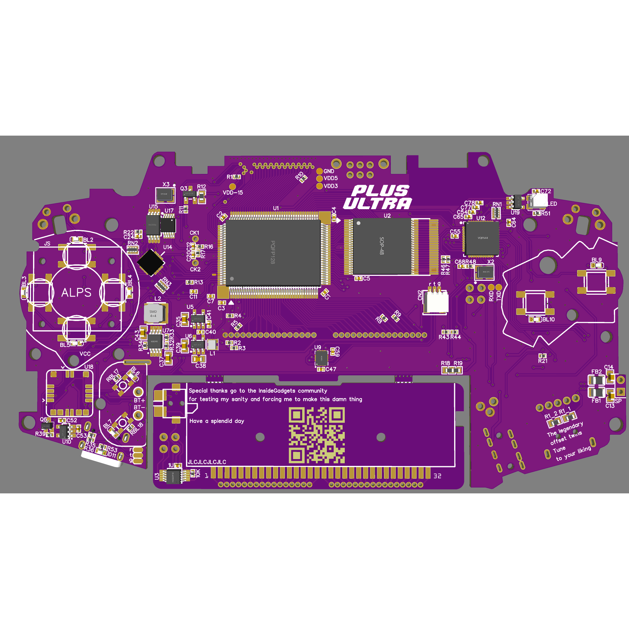
Let me get back to business, the GBA-2 Go. Mainly it's just an custom GBA PCB but with as many mods integrated as possible. Mod list will be near the end.

You went to look for the list didn't you, well not much has happened since you were gone. Lets continue, I started doing this project to learn more about electronics. Because what teaches better then learning from your own mistakes, especially if it costed you an arm and leg to build it.

Now you're wondering, that sounds great and all. But how did you emulate the AGB-CPU? Well to be honest. I didn't, I'm a hardware engineer not a software programmer. I just used the original CPU and SRAM. I decided to harvest the SRAM because a new one would be close to €10 a piece. And yeah, you already have to sacrifice a GBA when you want to make it.

Mods:

  • Gyroscope 
  • Accelerometer 
  • Variable clock 
  • NRF24L01
  • Tact switches
  • Button backlight
  • Multiple improvements: LiPo battery charger, new power button, USB, audio amp and possibility for 32 and 34 pin screens(GBA and GBA SP)+backlight control for the GBA SP and IPS kit ~Not in the trimmed version.
  • UDLR can also be swapped with an Joystick if you're not happy about it. ~Not in the trimmed version
  • Digital volume control

The trimmed version was brought to life to get an actual working prototype, instead of smacking together so much stuff you cant test properly. But mainly just to save time, I mean.. time is money..

It all is being controlled by an AtMega32u4 

If that doesn't impress you, then come with another mod that I could add to the list or to the GBA-3 (/DMGBA)

About GBA-2 Go, I named it Plus Ultra because.. yeah I am pushing the limit, kind off. But okey, GBA-2 Go Plus Ultra does sound nice

GBA2-DLF.pdf

The first 2 pages of the Schematic, the 3rd page(the Mods) is missing because I'm still cleaning it up, it quiet a mess. As you can see the schematic is not the final version

Adobe Portable Document Format - 343.22 kB - 04/28/2020 at 12:49

Preview
Download

Mods.pdf

The 3rd page of the schematic, I still need to renumber some parts and clean it up a bit more.

Adobe Portable Document Format - 212.34 kB - 05/09/2020 at 09:54

Preview
Download

Manual Nintendo gba2 - 32P.pdf

The trimmed version of the GBA schematic for the 32p models

Adobe Portable Document Format - 1.53 MB - 04/23/2020 at 08:33

Preview
Download

  • 05/06/2021 - I'm alive

    Derek F06/05/2021 at 19:23 0 comments

    After an almost year break due to covid *cough cough* yeah covid.

    Nah, to be honest. Ordered the boards, but it had some design flaws. Noticed them before building the boards luckily, so redid the design and simplified it a little. Removed some functions and feature but also some minor changes;

    • no more 2 types of LCD support, 
    • no more original LCD support(unless mod board is installed, see test points)
    • no power switch adapter board
    • changed all part to be SMT assembly compatible with my current fab house

    new deadline is to have a working version of the board before the end of the summer break.

    wish me luck

    (list will be updated with features that will remain in this version)

  • Whoops..

    Derek F10/14/2020 at 07:55 0 comments

    Well I kind off forgot this existed. Not that anyone is reading but hmm..

    Anyway, I've finished the boards. Yeah should've told you, I swapped the AtTiny for a Greenpak. Why you ask? -Just because I can, and I wanted to play with them for a while now. 

    So yeah the 2 PCBs have been ordered;

    The Greenpak Adapter board, although this euhm yeah went kind of wrong. So I've reordered them

    The GBA2 itself;


    So yeah all that remains is waiting for the PCBs and getting the parts. then hopefully I've got myself a working GBA2


  • 31/05/2020-Temporary break

    Derek F05/31/2020 at 12:02 0 comments

    "Huh, he hasn't updated his project in a while. He must have dropped it"

    "What happened? Did he just quite? Was it too hard for him?"

    and so on..

    Just kidding, anyway. 

    I kind of went quiet because my school exam continued. It's taking up way more time than I expected. Just 3 more weeks than I can continue with the GBA2.

    I promise I'll finish the GBA2 before the summer holiday starts. Atleast, that's my deadline.

  • 09/05/2020

    Derek F05/09/2020 at 09:12 0 comments

    It has been a while, the holiday came to an end so I had to work on my exam again. 

    After giving a whole speech on keeping it as cheap as possible in my last log I noticed there was a rather pricey part on the BOM. The ADXL335 would cost €5,50 a piece, combining that with the Gyroscope I was planning on using (L3GD20HTR) which would cost another €3,37. After doing some research I found a replacement for the ADXL, the LIS2DE12TR, which would only cost €1,34. Then I would save ≈€4. 

    While doing some research for my exam I came across a very interesting GitHub page Nintendo Switch Reverse Engineering, for my exam I was only interested in the way data was being sent from JoyCon > Switch and back. But for the GBA2 I was interested in what Gyroscope or Accelerometer they used, the LSM6DS3TR. Since it would only cost me €2,82 for the Gyroscope and Accelerometer, it would save me a whopping €6,05 a unit. So aside from being cheaper, saving me space, already being used so having a PoC(Proof of Concept), there's also already a library for it. Which would save me a lot of time. 

    I know I know, it's only a minor update. But I should be able to finish the first version in the next couple of days

    All that remains to be done is route the power path

  • 30/04/2020

    Derek F04/30/2020 at 19:47 0 comments

    Even though 90% of the schematic was complete there was still 1 part which wasn't complete. I've been pushing it forward ever since I started on the GBA2. Today was the day; I put on some good music, got myself a cup of coffee and got to work. And...

    well it didn't really go as planned, I think I wrote dozens of notes and possibly even more schematics. My Spotify playlist was already nearing the end of its 2nd round. Before I decided to quit the idea of a DDS/PWM driven Charge pump. It would just use too much space.

    So aside from

    • DDS/PWM driven Charge Pump

    There were the other options:

    1. Just picking a random Step Up and hooking a simple charge pump inverter to it
    2. a SIMO ic (Single Inductor Multiple Ouputs)
    3. Make my own switching regulator and hooking a simple charge pump inverter to it

    After reading the upper part of the log, you're probably wondering. 'What the heck was he trying to achieve?' good question, it's very simple. The 2 voltages specifically used by the original GBA LCDs. Hah! well if money grew on trees I wouldn't even have added support for it. 

    You probably went on a re-read, if you're actually interested at least or didn't quiet get the whole story.

    So I had 3 options left, looking back at it. Well to be honest the 3rd one was never gonna work. Let's be honest.. So the 1st and 2nd were the ones I was deciding between in the end. I drew both schematic and PCB design.

    option 1

    and option 2

    I liked both options, both used almost the same amount of space and both used parts that were easy to get my hands on. But well.. option 2 costed a bit more. The unit price of option 1 was €0,29 for the SU and €0,40 for the other parts. While option 2 the IC alone already costed €2. 

    So I decided to go with option 1 for the prototype, and if something were to go wrong with option 1; unstable voltage, noise, not being able to even reach the voltage etc. etc. Then I'll swap it with option 2 for the next revision

  • 27/04/2020

    Derek F04/27/2020 at 20:56 0 comments

    Decided to swap the pot-meter for a multi-direction slide switch

    This would allow for an easier control of stuff that need to be changed in steps; volume, back light, frequency and more.

    I though about adding a current source amplifier for the 34p (GBA SPs LCD) models to control the back light. But ended up with just a transistor and noted it down for a possible next revision. Freed up some IOs for IPS back light control and headphone button(you know the small ones halfway on the cord).

    Aside form these minor updates the design is coming along well. Just need to change almost all the part reference designators:

    Yeah.. I euh... no-one is perfect!

    As I'm having 2 weeks of holiday I'll be uploading more pics and info about the project. I kind of hijacked someone's discord and have been posting updates there for the past months

  • 23/04/2020

    Derek F04/23/2020 at 08:21 0 comments

    Minor setback, I had to redo the PCB design. 

    It just didn't quite fit. Also decided to make some changes:

    • Analog Joystick
    • DDS driven charge pump for 13.6v and -15v
    • Swapped the Gyroscope for a cheaper one
    • Added support for AA batteries
    • Overall component placement

View all 7 project logs

Enjoy this project?

Share

Discussions

sousa.nms wrote 07/12/2021 at 18:02 point

Hi Derek. I just wanted to compliment you on your project and execution so far. Looks very interesting and promissing. I have some questions if you don't mind.

I noticed that you aren't using the original GBA cartrige slot, but another later version (maybe from the NDS?) paired with a new GB/GBA cartridge detection switch. I also noticed that you created a riser board for it. Did you perform a fit test with a real cartridge on the GBA enclosure to see if all fits together?

Sorry for my ignorance, but what is the function of the following mods: Gyroscope, Accelerometer, Variable clock and NRF24L01?

Thank you and good work! :)

  Are you sure? yes | no

Derek F wrote 07/12/2021 at 18:14 point

Unless you're planning on desoldering the 36 pins of the original cartridge connector and be careful enough for it to be reusable then it's nearly impossible to do it right.

I went for the NDS slot simple because it's available, cheap and easily solder-able. The riser board is just a hit or miss, but because it's just a separate board I could always make some minor adjustments to it to make it fit perfectly. But by making it a separate board someone could always dev a built-in flashcard for it. By overriding the voltage switch you could tell the GBA to operate in 3v3 mode while running a GB(c) game, reducing overall cost price for carts as you wouldn't need level shifters that easily cost like €1 a piece. For now it just has more benefits to do it this way then to have to desolder the original connector, seeing how its one of the most common parts to fail nowadays(rust, and overal damage to the pins).

Those mods are just for whoever is planning on using them, increase game speed, play mario kart wii style, wireless controller etc.

Cheers

  Are you sure? yes | no

Famicombro wrote 06/01/2021 at 19:15 point

Hi, this looks very cool. Have you finished the project? Are the source files available?

  Are you sure? yes | no

Raizu wrote 07/16/2020 at 17:49 point

Whats the switch you used for the gb/gbc cartridge detection?

  Are you sure? yes | no

Derek F wrote 04/28/2020 at 17:32 point

If any of you have got questions or suggestions feel free to drop them here. Cheers

  Are you sure? yes | no

Similar Projects

Does this project spark your interest?

Become a member to follow this project and never miss any updates