 Thornhill!
Coding
After coming up against some memory allocation issues and then solving them with some optimisation and freezing some libraries, I've moved onto playing with the ItsyBity's nRF52840 chip and it's Bluetooth LE connection.
The main goal here is to be able to change text, images, and settings on the Psychic ePaper using a phone and a Bluetooth connection (imagine going to a convention, and being able to quickly customise an ID on the fly!). Fortunately with the CircuitPython BLE libraries and Adafruit's Bluetooth LE app, this has been very very easy. Using the example UART code from the CircuitPython BLE library and coding in a few key commands, I'm able to send messages to the Psychic and actively change text or swap images. Cosplaying as the 10th Doctor instead of the 12th? No problem! Just send the command [regenerate]10 and watch as the brooding face of David Tennant appears on the Psychic. Want to have the ID show you've been 'certified' by Rhe Convention of Doctors? Just send [title]The Convention of Doctors and it'll appear like it just read your mind!
The next step for me is storage, so that changes are not lost when the Psychic is turned off… and maybe a few advanced commands, like setting up the number and order of IDs. That'll be this week's goal!
Version 2 progress
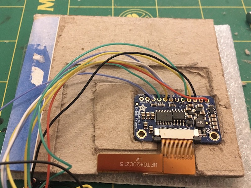
With version 2 I'm focusing on thinning things down and making construction easier and neater. I've started with the top half of the Psychic, which includes the e-ink display and adafruit's E-ink Friend. In version 1, both are embedded in a piece of paper/chipboard (the stuff hardback books are made out of… R.I.P Inorganic Chemistry textbook), and are connected to the micro-controller via a rat-nest of wires.
While this all works for a prototype, I think I can do a lot better for version 2!
So far for Version 2 I've:
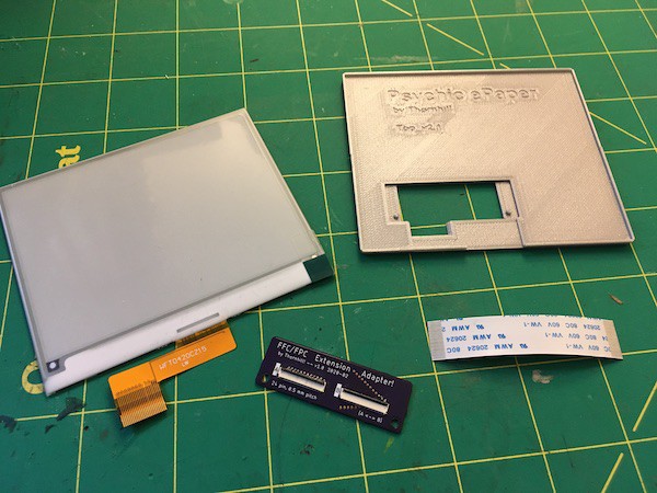
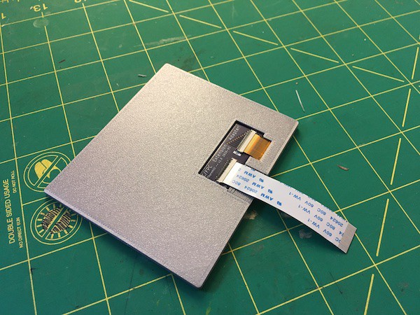
- Replaced the textbook cover with a 3D printed cover. It feels just as rigid and means I don't have to spend an hour carefully carving pockets and channels into the chipboard with an X-Acto knife. I've designed it so the display and components fit into it nicely, while protecting the FPC ribbon cables.
- Moved the E-Ink Friend to the bottom half of the Psychic. Am I moving my problems elsewhere? Sure, BUT… it allows me to make the top half of the Psychic really thin and reduces the whole rat-nest of wires. The bottom half of the psychic is the thicker of the two halves, so might as well lump stuff together. Future me can sort this out.
- Made a FPC/FFC adapter board. The display used to connect to the E-Ink Friend via it's FPC connector. I made an adapter board that the e-ink display connects to instead, while an adjacent FFC connector connects to a FFC ribbon cable to the E-ink Friend. This setup is a lot thinner, mostly because I ordered a thin (0.8 mm) and really thin (0.1016 mm!) PCB boards for the adapter. With some low profile FPC/FFC connectors, I've saved at least 3-4 mm.
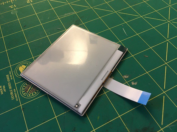
With all these changes, the top-half of the Psychic looks a lot neater and is now more reproducible. I'm going to have to see how durable the FFC cable is with the fold between the top and bottom half of the Psychic. Hopefully with the fabric and some strain relief, it won't be much of an issue!
That's it for this project update. Next: Designing a better bottom half!
Discussions
Become a Hackaday.io Member
Create an account to leave a comment. Already have an account? Log In.