 Adam Gulyas
I worked on this project at work in my spare time. My supervisor gave me permission to share it here.
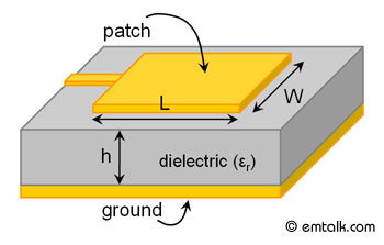
I wanted some experience designing antennas, so I started with the simplest one, a patch antenna. There were some initial goals:
- Since I was doing this at work, I designed it for the 2.4 GHz ISM band which is what our proprietary wireless protocol uses
- Use a PCB as the only component, since they're cheap and easy to design
- Transmit 90% of the input energy. (S11 ≤ -10 dB)
- I'm ignoring antenna losses for now since I don't know of a way to measure them without an antenna chamber.
- Input impedance of 50 Ω
Design
I found some design equations in the textbook Antenna Theory: Analysis and Design 3rd Edition, pp 816-820, equations 14-1 to 14-7. I created a spreadsheet titled Patch Antenna Calculator to calculate the equations, which yielded the following results:
| INPUTS | |
| relative dielectric constant of the substrate | 4.7 (FR-4) |
| dielectric height | 1.6 mm |
| frequency | 2.44 GHz |
| OUTPUTS | |
| width | 36.415 mm |
| length | 28.021 mm |
I've uploaded the spreadsheet in the Downloads section of this project.
These results agree with this online calculator: emtalk.com/mpacalc
A PCB was designed in Altium with these dimensions:
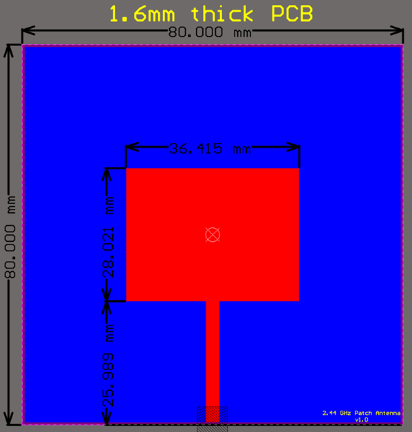
The length of the wave guide feeding the patch antenna was chosen arbitrarily, since it should all be 50 Ω until it meets the patch.
The edge connector details are:
| Digi-Key Part Number | SAM8857-ND |
| Manufacturer | Samtec Inc. |
| Manufacturer Part Number | SMA-J-P-H-ST-EM1 |
| Description | SMA Connector Jack, Female Socket 50Ohm Board Edge, End Launch Solder |
| price/unit @1 (Nov 25, 2019, Digi-Key) | $4.33 |
The PCB was added to an order going to JLCPCB, so it only cost $2 to get 5 samples.
Results
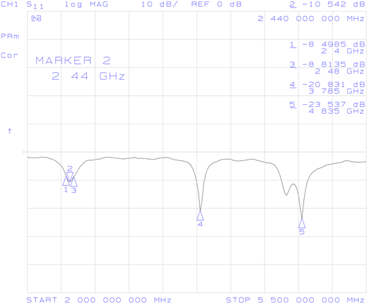
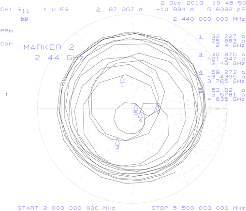
Connecting the antenna to a VNA gave the following plots:
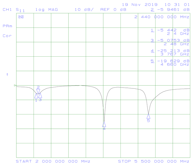

It can be seen that, while the antenna is resonant at 2.44 GHz, S11 is only around -5 dB and the input impedance is 123 + j57 Ω, which are both too high. Surprisingly, the antenna is also resonant at 3.767 GHz and 4.66 GHz, both of which show a better input impedance than the design frequency.
The energy at those two higher frequencies is disappearing into the antenna, but is it actually being radiated? To quickly test this, I connected antenna samples to both ports of the VNA and put them next to each other. 2.44 GHz had the highest S21 value, with the other two frequencies responding much more weakly. While this test wasn't nearly as rigourous as using a test chamber, it does suggest that the higher frequencies aren't actually resonating.
Simulation
After this puzzling result, the antenna was also simulated in Keysight Genesys, yielding this S11 plot:
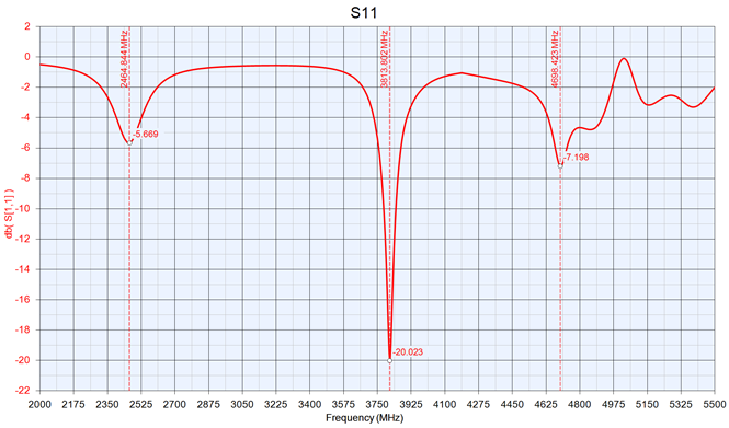
It's resonant at 2.46 GHz instead of 2.44 GHz. It also shows the three resonant dips at roughly the same frequencies, although the higher frequency results differ wildly.
Analysis
Asking in an online forum why the antenna S11 wasn’t lower at 2.44 GHz and why the extra resonances were observed yielded this comment:
“You're probably getting the intended patch mode, a transmission line mode, and maybe edge modes at the bottom of the patch. Total conjecture, would have to sim it to see where the current is popping up.”
Searching online for answers led to this link: http://www.antenna-theory.com/antennas/patches/patch3.php
“Previously, the patch antenna was fed at the end as shown here. Since this typically yields a high input impedance, we would like to modify the feed. Since the current is low at the ends of a half-wave patch and increases in magnitude toward the center, the input impedance (Z=V/I) could be reduced if the patch was fed closer to the center.”
http://www.antenna-theory.com/antennas/patches/patch4.php
- the length of the patch L controls the resonant frequency
- increasing the height of the substrate increases the bandwidth
- the width W controls the input impedance and the radiation pattern (wider = lower input impedance)
Based on this information, I decided that a better way to feed the antenna was needed. Once again, antenna-theory.com had some good information, showing two promising methods:
From http://www.antenna-theory.com/antennas/patches/patch3.php
Inset Feed
Previously, the patch antenna was fed at the end as shown here. Since this typically yields a high input impedance, we would like to modify the feed. Since the current is low at the ends of a half-wave patch and increases in magnitude toward the center, the input impedance (Z=V/I) could be reduced if the patch was fed closer to the center. One method of doing this is by using an inset feed (a distance R from the end) as shown in Figure 1.

Since the current has a sinusoidal distribution, moving in a distance R from the end will increase the current by cos(pi*R/L) - this is just noting that the wavelength is 2*L, and so the phase difference is 2*pi*R/(2*L) = pi*R/L.
The voltage also decreases in magnitude by the same amount that the current increases. Hence, using Z=V/I, the input impedance scales as:

In the above equation, Zin(0) is the input impedance if the patch was fed at the end. Hence, by feeding the patch antenna as shown, the input impedance can be decreased. As an example, if R=L/4, then cos(pi*R/L) = cos(pi/4), so that [cos(pi/4)]^2 = 1/2. Hence, a (1/8)-wavelength inset would decrease the input impedance by 50%. This method can be used to tune the input impedance to the desired value.
Coaxial Cable or Probe Feed
Microstrip antennas can also be fed from underneath via a probe as shown in Figure 3. The outer conductor of the coaxial cable is connected to the ground plane, and the center conductor is extended up to the patch antenna.
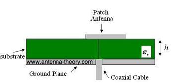
The position of the feed can be altered as before (in the same way as the inset feed, above) to control the input impedance.
The coaxial feed introduces an inductance into the feed that may need to be taken into account if the height h gets large (an appreciable fraction of a wavelength). In addition, the probe will also radiate, which can lead to radiation in undesirable directions.
Changing The Feed Method
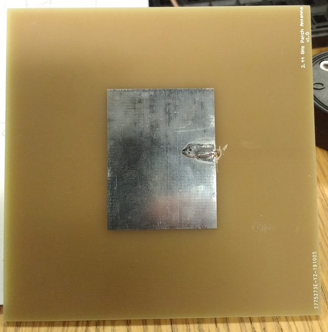
I took one of the PCBs I made and cut off the wave guide, leaving just the patch antenna. Then I fed it with a coax feed, as shown above, at the very edge of the antenna to find Zin(0).
This gave the following plots:
So, Zin(0) = 87.367 - j10.984 Ω
I probably should have used the magnitude for this calculation (88.05 Ω) , but I just took the real part. Using the equation
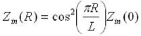
gives
| Zin(0) | 87.367 |
| R/L | 0.2269 |
| Zin | 50.00 |
Here, L = 28.021 mm, so R = 28.021 * 0.2269 mm = 6.358 mm, where R is the insert distance.
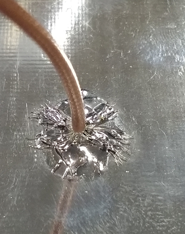
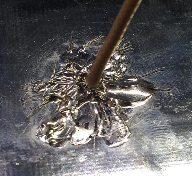
With the insert distance determined, I roughly modified another antenna to confirm this approach:
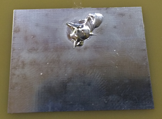
You can see that I spread out the center conductor wires. The hole I drilled was far too large for this purpose, and I’m worried that having that big of a gap affected the measurements. However, I didn't have any smaller drill bits.
This gave the following results:
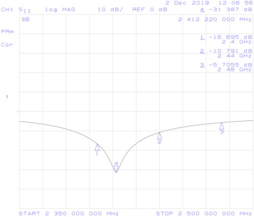

That improved things a lot. Minimum S11 is -31 dB, which is great, and minimum input impedance is 52.47 + j1.39 Ω. However, at 2.48 GHz S11 only goes down to -5.7 dB which is too high. The resonant frequency is in the wrong point, probably due to the imprecise hole I drilled. If the frequency is increased, the whole band might get under -10 dB.
Future Work
The next step is to get another prototype made with a precisely drilled small hole, then tweak the patch length to shift the resonant frequency. If, even with the frequency in the middle of the ISM band, S11 isn't low enough, the bandwidth could be increased by making the PCB thicker.