DIY GUY Chris
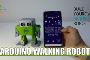
Hey guys! I Hope you already enjoyed my previous project "ELECTRONIC CHRISTMAS TREE" and you are ready for a new one, as usual I made this tutorial to guide you step by step while you make your own robot and to start learning how controlable robots are made and how to control them as well, this project could be a great start in robotics world.
During the making of this project, we tried to make sure that this instructable will be the best guide for you in order to help you if you want to make your own robot, so we hope that this instructable contain the needed documents. This project is so handy to make specially after getting the customized PCB that we’ve ordered from JLCPCB to improve the appearance of our electronic device and also there is enough documents and codes in this guide to allow you create your beautiful robot. We've made this project in just 4 days only, just one days to get all the needed parts and finish the hardware making and the assemble, then one day to prepare the code to suit our project and two days to create the android app then we have started the testing and the adjustments.
What you will learn from this instructable:
- Making the right hardware selection for your project depending on its functionalities.
- Understand the robot mecanisme.
- Prepare the circuit diagram to connect all the choosen components.
- Solder the electronic parts to the PCB.
- Assemble all the project parts (robot body).
- Start the first test and validate the project.
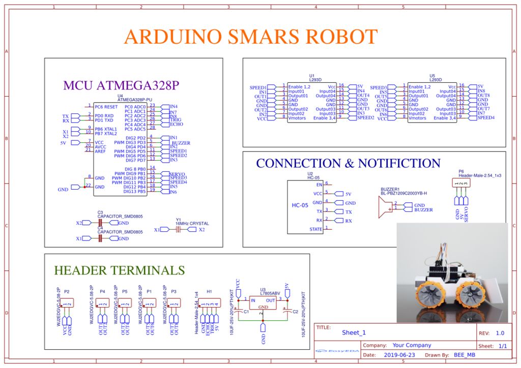
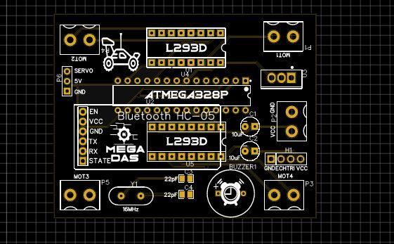
Step 1: Circuit Diagram
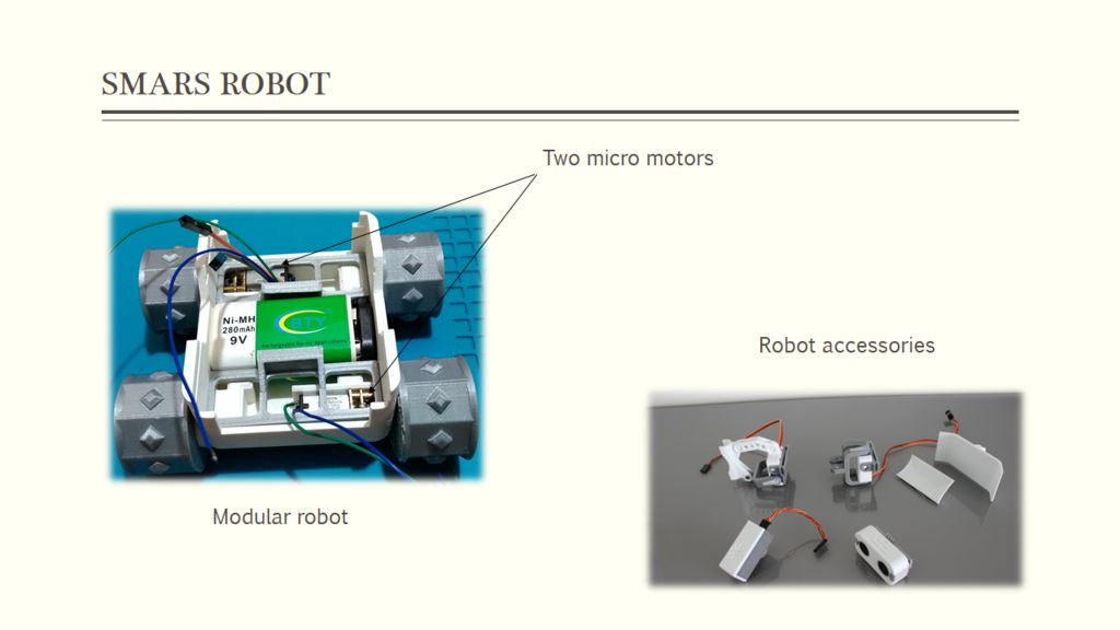
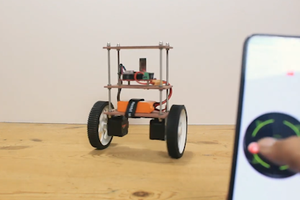
As always guys, I try to pick up some easy projects for the audience so everyone can try it and today’s project is easy as well, based on the 3D printed parts of the SMARS robot which is a small vehicle with two micro motors and there is lots of designs that you can follow to make your own robot, and also about the accessories that you can add to your robot they are many but for our project we will start with the basic design so no much accessories in it, but we will post in the coming videos how to add more features to our small robot.
Moving to the control part, as it show the circuit diagram above, we will use an ATmega328 MCU that you can have from the Arduino UNO board, this MCU is driving the two micro motors through L293 H-bridge driver and as you can see I added two motor drivers so you can use this circuit diagram in case your robot is a four motors robot, also we have a buzzer output a servo motor output control, the Bluetooth connection pins and a ultrasonic sensor input, all these are features that you can play with when you produce the same circuit diagram.
Just one last component is the 5V voltage regulator which is required in here since we are using a 9V battery to power the robot and we need to dorp down the voltage to 5V for the power supply of the MCU and the motors.
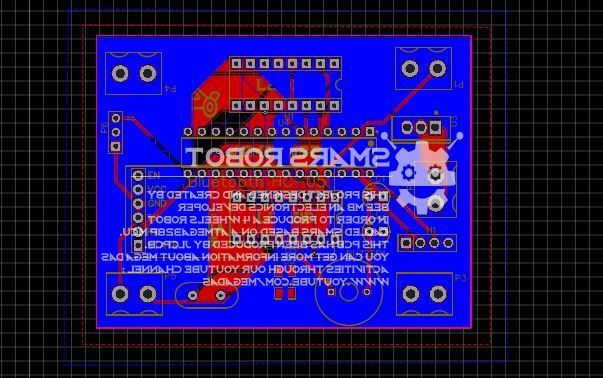
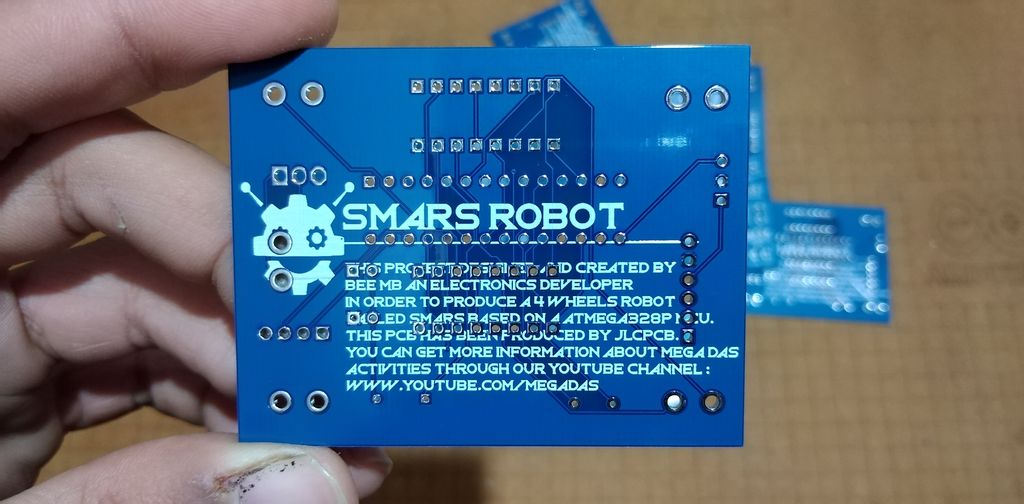
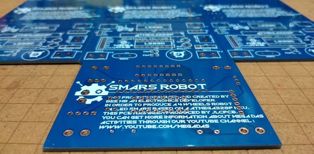
Step 2: PCB Making


About JLCPCB
JLCPCB (Shenzhen JIALICHUANG Electronic Technology Development Co., Ltd.), is the largest PCB prototype enterprise in China and a high-tech manufacturer specializing in quick PCB prototype and small-batch PCB production. With over 10 years of experience in PCB manufacturing, JLCPCB has more than 200,000 customers at home and abroad, with over 8,000 online orders of PCB prototyping and small quantity PCB production per day. The annual production capacity is 200,000 sq.m. for various of 1-layer, 2-layer or multi-layer PCBs. JLC is a professional PCB manufacturer featured of large scale, well equipment, strict management and superior quality.
Talking electronics
After preparing the circuit ,I transformed it into a customized PCB design and the easiest task now is to place the order for the PCBs so I need is to move to JLCPCB the best PCB supplier in order to get the best PCB manufacturing service, as always just some simple clicks that’s all what you need to uploaded the GERBER files of the circuit design then I moved to set some parameters and this time we...
Read more »
 Mrinnovative
 Jithin Sanal