 Trevor R.H. Clarke
Here's my initial take on an overall design.
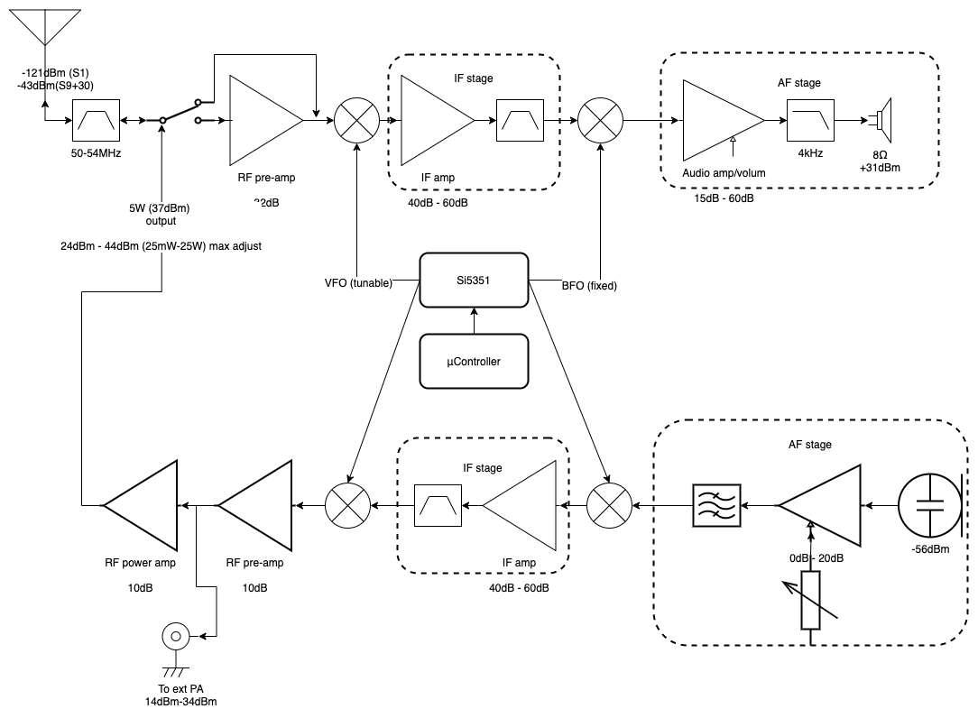
My general philosophy for this transceiver is to simplify the RF and AF sides using as many inexpensive ICs and MMICs as possible and focus my design efforts on eeking out low noise gain in the IF.
Receiver chain
The receiver is designed to handle about S1 to S9+30 dynamic range. (I'm assuming -73dBm for S9) 6m environmental noise is most likely higher than S9 in my area so this might be relaxed. A crystal band filer across the entire US 6m allocation feeds into an optional RF LNA. This will probably be an inexpensive MMIC with low noise and low distortion.
I'm leaning towards an IF in the 700-700MHz range or in the 165MHz range. This should be low enough that it's not terribly sensitive to board impedance issues but high enough to make use of SAW filters. Since ultra-narrow SAW filter bandwidths are still in the 100s kHz but they are quite frequency stable, I'm going to try and use two overlapping filters to tighten the bandwidth enough. Utilizing SAW filters has the benefit of very low noise and low insertion loss for low cost. These are also common mobile telephone frequencies so SAW filters are widely available. The multi-stage IF amp is adjustable by about 20dB for AGC use. This should be easily achievable with a single adjustable gain block.
The audio section will be a basic audio power amp for whatever speaker I have around, something in the 1.5W-5W range. I've got a bunch of audio opamps of various types so I'll probably play around with a few to find a decent low-noise option. Being a 60dB gain block this will have two to three stages depending on how clean the opamps are at the 30dB level.
Transmit chain
An electret mic will be targeted followed by a trimmer adjustable gain block. This will make it easier to adjust for different mic sensitivities. I put a generic filter as I'm not sure if I'm going to have a gain block followed by a passive LPF or if I'm just going to implement an active BPF.
I'm initially thinking about using the same IF chain and reversing it on transmit to cut down on component count and cost but these designs can be susceptible to bleed over from the TX side to the RX side. I'm thinking the mixers, Si5351, and IF chain will be inexpensive enough that I can include a separate TX IF if necessary.
A pre-amp should boost levels to about 25mW which should be able to drive an external 50W amp via a tap or drive an internal 5W PA. If this is a bit high, I'll include a 10dB or so attenuator.
The TX side uses the same BPF as the RX side before hitting the antenna.
CW operation
CW isn't represented in the diagram yet. I'm not sure if the overlapping SAW filter technique will be able to create a CW filter that is usable a the high IF so I may implement that as a separate BPF in the baseband. Adjusting the BFO should be enough to decode the CW with an adjustable tone frequency.
The transmit side will probably be a direct driven transmit. There's a third Si5351 output which can be adjusted to the transmit frequency plus the adjustable tone frequency. I'm not sure if the clock output can be switched on and off easily enough to use that as the CW generator or if I'll include a PIN diode RF switch.
There's the question of keying harmonics and bandwidth to deal with. I'll have to analyze the spectrum of a worst-case transmision. (I'll use 30wpm continuous dits) If the bandwidth is not satisfactory I'll have to switch to an AF generator and use a gaussian LPF to clean up the signal.
Digital blocks
I'm going to use a stock standard Si5351A board for generating the LOs. This will be controlled by a microcontroller. I have a plethora of options on hand but I'm partial to ST devices so I'll likely use a low cost STM32. I've also got a few multi-line LCD displays and various encoders and buttons to use for I/O.
Discussions
Become a Hackaday.io Member
Create an account to leave a comment. Already have an account? Log In.