 Marcin Saj
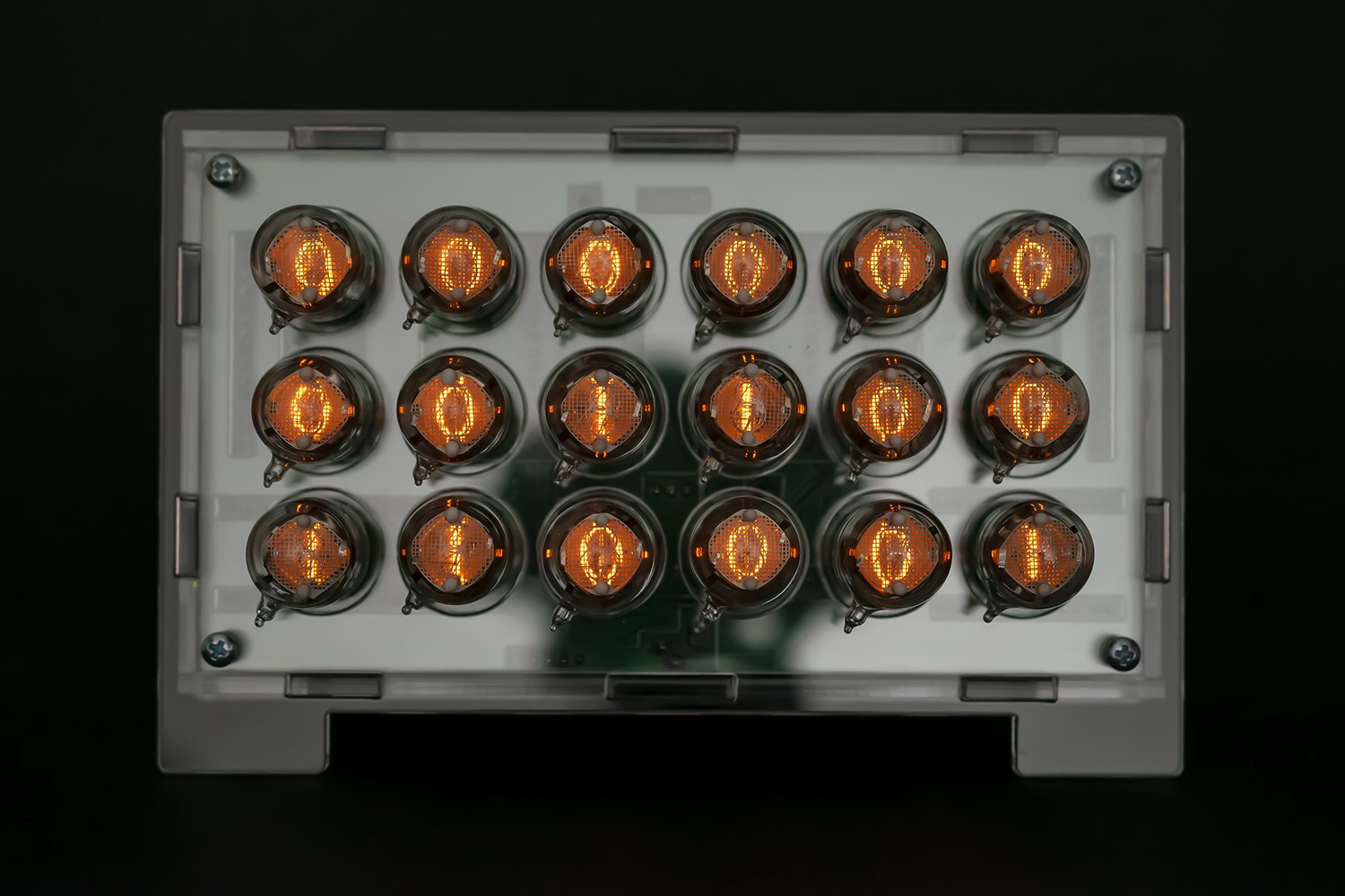
FEATURES & COMPONENTS.
- Compatible with 5V/3.3V boards – Arduino Nano, Nano Every, Nano 33 IoT and Particle Photon
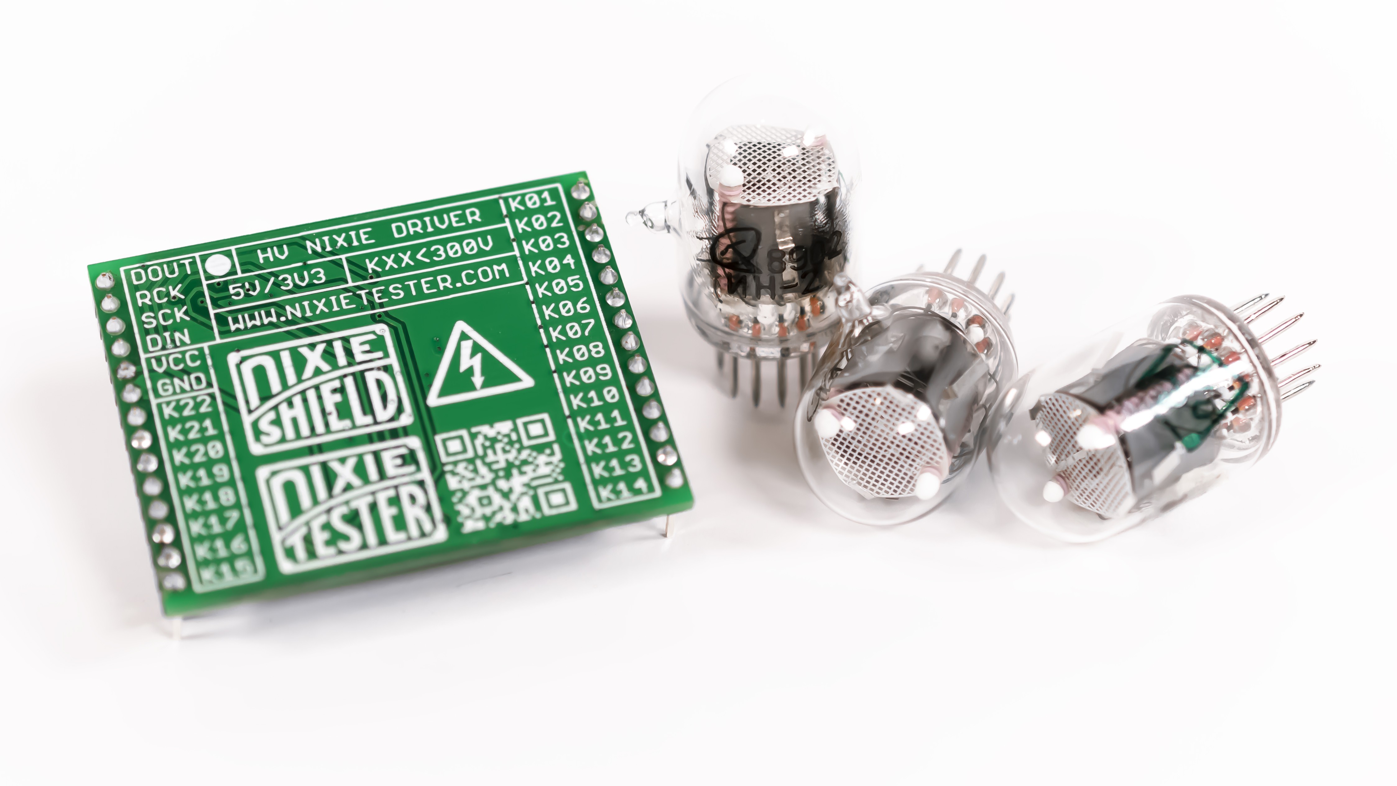
- Replaceable IN-2 nixie tubes – pin socket connectors
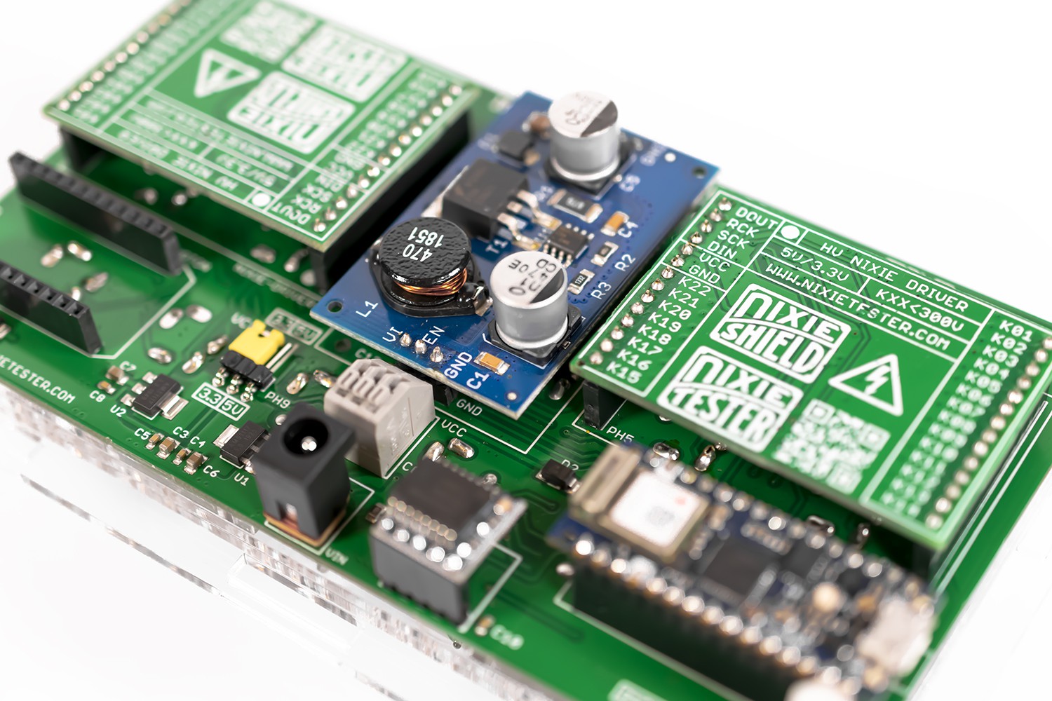
- Modular design
- RTC real time clock DS3231 module on board
- Nixie power supply module 170V (fully assembled) included
- 2 x Nixie Tube Driver V2 (fully assembled) – on board
- Designed to work with DHT22/DHT11 temperature & humidity sensor
- Assembled all SMD components
- Connectors, pin headers and nixie tubes sockets require soldering
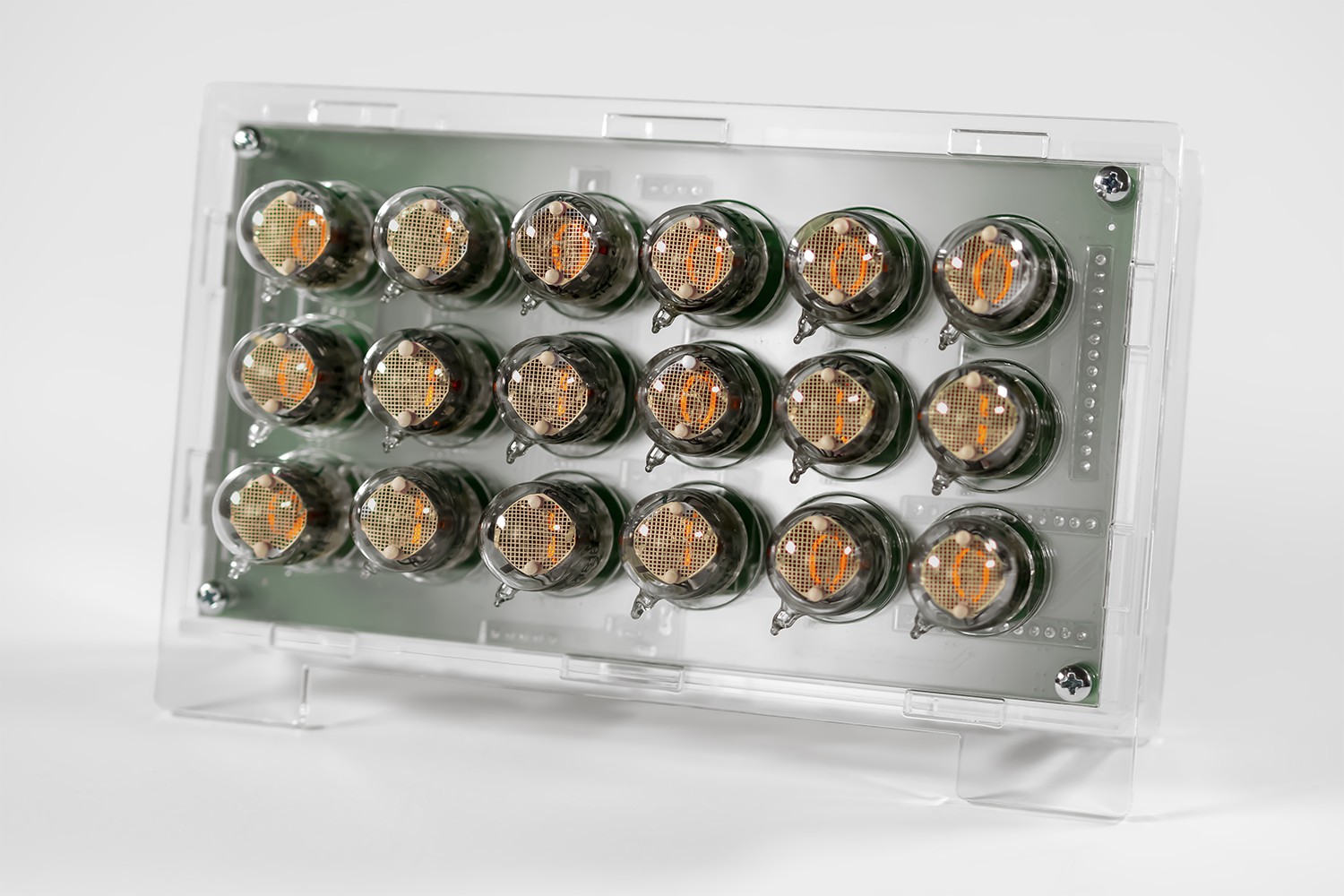
- Dimensions with tubes: 60 x 108 x 167 mm (~2.4″ x 4.3″ x 6.6″)
- External power supply required (Arduino Vin connector): 12V; 1A DC; plug diameter 2.5 x 5.5 mm; center pin positive+
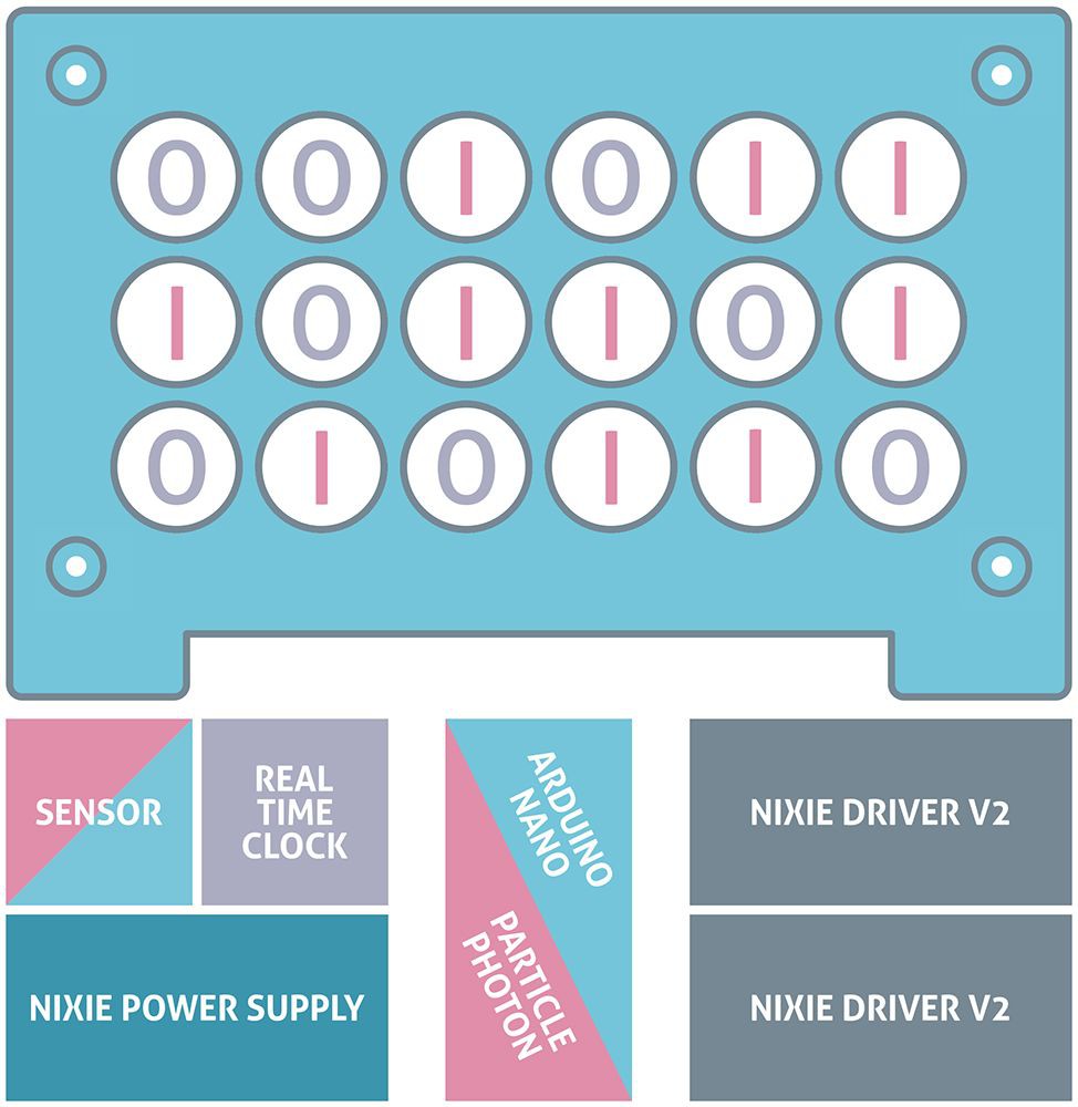
HOW IT'S MADE.
The modular design allows easy and quick assembly. Individual modules are placed in specific slots.
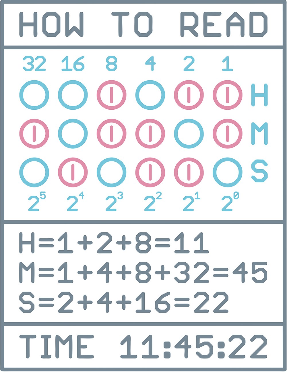
BINARY CODE.
Binary code is a base 2 number system invented by Gottfried Leibniz where numeric values are represented by different combinations of 0 and 1, also know as OFF or ON. Is the simplest form of computer code or programming data.
SCHEMATIC.
CODING.
The program code has been prepared:
- Classic Binary Clock – Arduino Nano, Nano Every, Nano 33 IoT
- WiFi NTP Binary Clock – Arduino Nano 33 IoT
- WiFi Particle Cloud Binary Clock – Particle Photon
DATASHEET.
Datasheet can be found on GitHub repository.
CODE EXPAMPLES.
// IN-2 Binary Nixie Clock by Marcin Saj https://nixietester.com
// https://github.com/marcinsaj/IN2-Binary-Nixie-Clock
//
// Classic IN-2 Binary Nixie Clock Example
//
// This example demonstrates how to set the RTC time, read time from RTC and display on nixie tubes.
// Serial monitor is required to display basic options.
//
// Hardware:
// IN-2 Binary Nixie Clock - https://nixietester.com/project/in-2-binary-nixie-clock/
// Arduino Nano - https://store.arduino.cc/arduino-nano
// Or Arduino Nano Every - https://store.arduino.cc/arduino-nano-every
// Or Arduino Nano IoT 33 - https://store.arduino.cc/arduino-nano-33-iot
// Nixie Power Supply Module, 2 x Nixie Tube Driver V2 & RTC DS3231 module
// Nixie clock require 12V, 1A power supply
// Schematic IN-2 Binary Nixie Clock - http://bit.ly/IN2-BNC-Schematic
// Schematic Nixie Tube Driver V2 - http://bit.ly/NTD-Schematic
// Schematic Nixie Power Supply Module - http://bit.ly/NPS-Schematic
// DS3231 RTC datasheet: https://datasheets.maximintegrated.com/en/ds/DS3231.pdf

#include            // https://github.com/adafruit/RTClib

#define EN_NPS    A3          // Nixie Power Supply enable pin - "ON" = 0, "OFF" = 1
#define DIN_PIN   A2          // Nixie driver (shift register) serial data input pin
#define CLK_PIN   A1          // Nixie driver clock input pin
#define EN_PIN    A0          // Nixie driver enable input pin

// Choose Time Format
#define HH        24          // 12 Hour Clock or 24 Hour Clock

// Bit numbers declaration for nixie tubes display
//           32  16   8   4   2   1
byte H1[] = {26, 24, 45, 15, 17, 12};     // "1" Hours
byte H0[] = {27, 25, 44, 14, 16, 13};     // "0" Hours
byte M1[] = {34, 28, 43, 19, 10,  8};     // "1" Minutes
byte M0[] = {35, 29, 42, 18, 11,  9};     // "0" Minutes
byte S1[] = {36, 39, 41, 21,  2,  0};     // "1" Seconds
byte S0[] = {37, 38, 40, 20,  3,  1};     // "0" Seconds

// 18 bits for "1", 18 bits for "0" - check clock schematic
// 8 bits for gaps - nixie drivers not connected outputs
// 2 bits for nixie driver gaps - check driver schematic

// Nixie Display bit array
boolean nixieBitArray[46];

// Serial monitor state
boolean serialState = 0;

// Millis delay time variable
unsigned long previous_millis = 0;

// RTC library declaration
RTC_DS3231 rtc;


void setup()
{
  Serial.begin(9600);
  rtc.begin();
  delay(3000);

  pinMode(EN_NPS, OUTPUT);
  digitalWrite(EN_NPS, HIGH);   // Turn OFF nixie power supply module

  pinMode(DIN_PIN, OUTPUT);
  digitalWrite(DIN_PIN, LOW);

  pinMode(CLK_PIN, OUTPUT);
  digitalWrite(CLK_PIN, LOW);

  pinMode(EN_PIN, OUTPUT);
  digitalWrite(EN_PIN, LOW);

  Serial.println("#############################################################");
  Serial.println("------------------ IN-2 Binary Nixie Clock ------------------");
  Serial.println("---------------- If you want to set new Time ----------------");
  Serial.println("--------------- press ENTER within 5 seconds ----------------");

  // Millis time start
  unsigned long millis_time_now = millis();
  unsigned long millis_time_now_2 = millis();

  // Wait 5 seconds
  while((millis() < millis_time_now + 5000))
  {
    // Print progress bar
    if (millis() - millis_time_now_2 > 80)
    {
      Serial.print("#");
      millis_time_now_2 = millis();
    }

    // Set serialState flag if time settings have been selected
    if(Serial.available() > 0)
    {
      serialState = 1;
      break;
    }
  }

  Serial.println('\n');

  // Clear serial buffer
  while(Serial.available())
  Serial.read();

  if(serialState == 0)
  {
    // Turn on the nixie power module if settings have not been selected
    digitalWrite(EN_NPS, LOW);
  }
}


void loop ()
{
  // Set a new time if settings have been selected
  if(serialState == 1)
  {
    SetNewTime();
    serialState = 0;

    // Turn ON nixie power supply module
    digitalWrite(EN_NPS, LOW);
  }

  // Millis time start
  unsigned long current_millis = millis();

  // Wait 1 second
  if(current_millis - previous_millis >= 1000)
  {
    previous_millis = current_millis;

    // Get time from RTC and display on nixie tubes
    DisplayTime();
  }
}

void SetNewTime()
{
  Serial.println("------ Enter the TIME without spaces in the HHMM format ------");
  Serial.println("- and press enter when you are ready to send data to the RTC -");
  Serial.println('\n');

  // Clear serial buffer
  while(Serial.available())
  Serial.read();

  // Wait for the values
  while (!Serial.available()) {}

  // Read time as an integer value
  int hhmm_time = Serial.parseInt();

  // Extract minutes and hours
  byte timeSecond = 0;
  byte timeMinute = (hhmm_time / 1) % 100;
  byte timeHour   = (hhmm_time / 100) % 100;

  rtc.adjust(DateTime(0, 0, 0, timeHour, timeMinute, 0));
}

void DisplayTime()
{
  DateTime now = rtc.now();

  byte timeHour = now.hour();
  byte timeFormat = HH;

  // Check time format and adjust
  if(timeFormat == 12 && timeHour > 12) timeHour = timeHour - 12;
  if(timeFormat == 12 && timeHour == 0) timeHour = 12;

  byte timeMinute = now.minute();
  byte timeSecond = now.second();

  Serial.print("Time: ");
  if(timeHour < 10)   Serial.print("0");
  Serial.print(timeHour);
  Serial.print(":");
  if(timeMinute < 10) Serial.print("0");
  Serial.print(timeMinute);
  Serial.print(":");
  if(timeSecond < 10) Serial.print("0");
  Serial.println(timeSecond);

  NixieDisplay(timeHour, timeMinute, timeSecond);
}

void NixieDisplay(byte hours, byte minutes, byte seconds)
{
  boolean bitTime = 0;

  for (int i = 45; i >= 0; i--)
  {
    // Clear bit array
    nixieBitArray[i] = 0;
  }

  for(int i = 5; i >= 0; i--)
  {
    bitTime = hours & B00000001;                  // Extraction of individual bits 0/1
    hours = hours >> 1;                           // Bit shift

    if(bitTime == 1) nixieBitArray[H1[i]] = 1;    // Set corresponding bit
    else nixieBitArray[H0[i]] = 1;

    bitTime = minutes & B00000001;                // Extraction of individual bits 0/1
    minutes = minutes >> 1;                       // Bit shift

    if(bitTime == 1) nixieBitArray[M1[i]] = 1;    // Set corresponding bit
    else nixieBitArray[M0[i]] = 1;

    bitTime = seconds & B00000001;                // Extraction of individual bits 0/1
    seconds = seconds >> 1;                       // Bit shift

    if(bitTime == 1) nixieBitArray[S1[i]] = 1;    // Set corresponding bit
    else nixieBitArray[S0[i]] = 1;
  }

  ShiftOutData();
}

void ShiftOutData()
{
  // Ground EN pin and hold low for as long as you are transmitting
  digitalWrite(EN_PIN, 0);
  // Clear everything out just in case to
  // prepare shift register for bit shifting
  digitalWrite(DIN_PIN, 0);
  digitalWrite(CLK_PIN, 0);

  // Send data to the nixie drivers
  for (int i = 45; i >= 0; i--)
  {
    // Send current bit
    if(nixieBitArray[i] == 1) digitalWrite(DIN_PIN, HIGH);
    else digitalWrite(DIN_PIN, LOW);
    // Register shifts bits on upstroke of CLK pin
    digitalWrite(CLK_PIN, 1);
    // Set low the data pin after shift to prevent bleed through
    digitalWrite(CLK_PIN, 0);
  }

  // Return the EN pin high to signal chip that it
  // no longer needs to listen for data
  digitalWrite(EN_PIN, 1);

  // Stop shifting
  digitalWrite(CLK_PIN, 0);
}