Schmid Lukas
Important:
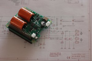
There is a littel production error. The GND Connection of the D1, U1 and L1 aren't done correctly. So to make the step-down converter work, simply solder a GND bridge on top of the pins of the step-down converter, like seen on the Picture.
What is it?
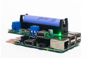
This is the imporved Raspberry Pi HAT based on my other product: HAT rev1.0
This stepper driver HAT has an additional step-down converter on it. so it's possible to run the driver at a higher voltage and get the benefit to simultaneously power the Raspberry Pi at 5VDC. No additional 5V power supply necessarily.
Features
- Barrel jack for power input
- Step-down convertor (10-30VDC to 5VDC)
- On/Off switch
- 1 JST XH-4A for 4 wire connection to stepper motor
- 3 JST XH-3A connector for GPIOS (5V, GND, GPIO)
- Pin Headers for 5V and GND
- Pin Headers and resistor-array for LEDs
- socket for DRV8825 or a4988 stepper driver
Voltage
- Input voltage: 10-30VDC
- Output voltage: 5VDC (for Raspberry Pi)
- Stepper driver voltage: Same as input voltage (10-30VDC)
Why did you make it?
I made it for my own project. a simple vending machine, which is driven by a NEMA17 stepper motor. I built it based on my first version of the PCB, which had no step-down converter. The Main reason i made a second version was so i could power the Raspberry Pi and the stepper driver/motor with a single power supply.
What makes it special?
It's a two in one stepper driver HAT and step-down converter. Simply power motor and driver at a higher voltage, like 24VDC and let the onboard step-down converter supply the 5VDC for the Raspberry Pi
 tonyjanugrah