Arduino KIT
Overview of photosensitive light sensors (CDS)
Optical light sensor changes resistance based on the intensity of the light being illuminated, the sensor uses Photoresistor so the sensitivity is high, the signal is stable.
Advantages
- Compact circuit design.
- High precision.
- Flexibility in adjusting the sensitivity of the sensor (through the resistor is integrated on the circuit).
- Note:
- To understand more about how the digitalRed () function works, see this article: See now. Turning the clockwise will reduce the recognition intensity of the sensor, ie the environment must be less light for the sensor to read digitalRead () value as 1.
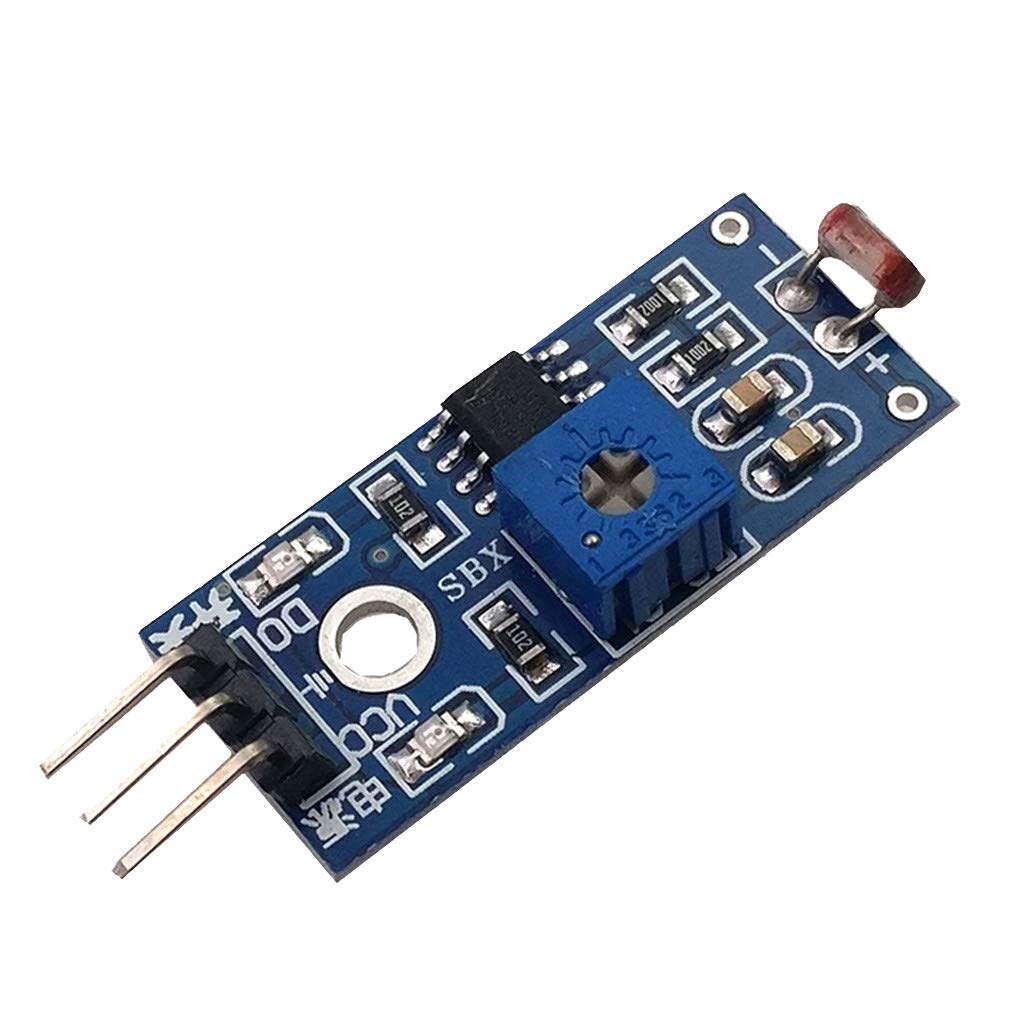
The function pins
VCC | Positive power supply for the Sensor (3V3 - 5V) |
GND | Mass connector |
D0 | Digital I / O signal output |
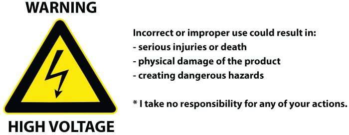
Attention when using
In order to continue the article, we advise you to be careful in connecting, to avoid injury.
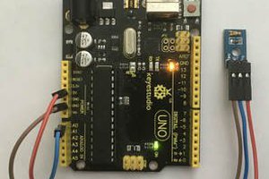
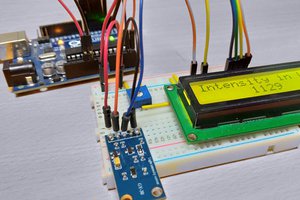
Connection diagram

The necessary components for the project
- Arduino Uno: >> See product here
- Light sensor module: >> See product here
- Relay 1 channel module (5VDC): >> See product here
Code
 / *
* This is the Arduino code for Light module for Arduino (basic)
This video shows you how to turn an AC light ON during the night using Light sensor
and turn it OFF during the day. This code is basic version where
digital output of the module is used.
// Written for Robojax.com video

* watch HC-SR505 Motion Sensor video for details https://youtu.be/qhThpxiXubI
 * Code is available at http://robojax.com/learn/arduino

 *
// Writeen by Ahmad S . for Robojax.com on
// on Freb 10, 2018 at 13:43 at city of Ajax, Ontario, Canada
* /
#define  LIGHT  7  // define pint 7 for sensor
#define  RELAY  4 // define pin 4 as for relay

/ *
* Permission granted to share this code given that this
* note is kept with the code.
* Disclaimer: this code is "AS IS" and for educational purpose only.
*
* /

void  setup ( )  {
  // Light LDR Sensor Code by Robojax.com 20180210
  Serial . begin ( 9600 ) ; // setup Serial Monitor to display information
  pinMode ( LIGHT ,  INPUT_PULLUP ) ; // define pin as Input sensor
  pinMode ( RELAY ,  OUTPUT ); // define pin as OUTPUT for relay
}

void  loop ( )  {
  // Light LDR Sensor Code by Robojax.com 20180210
  int  L  = digitalRead ( LIGHT ) ; // read the sensor

    if ( L  ==  1 ) {
    Serial . println ( "light is ON" ) ;
    digitalWrite ( RELAY , LOW ) ; // turn the relay ON
  } else {

     Serial . println ("=== light is OFF" ) ;
     digitalWrite ( RELAY , HIGH ) ; // turn the relay OFF
  }
  delay ( 500 ) ;
 // Light LDR Sensor Code by Robojax.com 20180210
}
Explain the Code
As always, the first step we go into declaring pins for each device.
#define LIGHT 7 // define pint 7 for sensor #define RELAY 4 // define pin 4 as for relay
Next, in the Loop (), we set the variable L as the value to read the sensor.
If the optical light sensor is getting a value of 1.
Note: At this time the light sensor will receive the value of level 1 when in low light environment.
Then the relay will close and make the light on and vice versa.
void  loop ( )  {  // Light LDR Sensor Code by Robojax.com 20180210 int L = digitalRead ( LIGHT ) ; // read the sensor if ( L == 1 ) { Serial . println ( "light is ON" ) ; digitalWrite ( RELAY , LOW ) ; // turn the relay ON } else { Serial . println ( "=== light is OFF" ) ;
  digitalWrite ( RELAY , HIGH ) ; // turn the relay OFF  }  delay ( 500 ) ;  // Light LDR Sensor Code by Robojax.com 20180210 }
 hIOTron
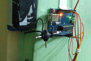
 Adnan.R.Khan
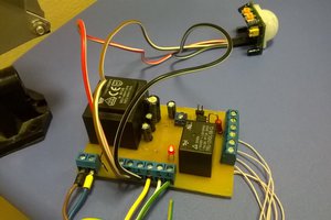
 Osman Mazinov