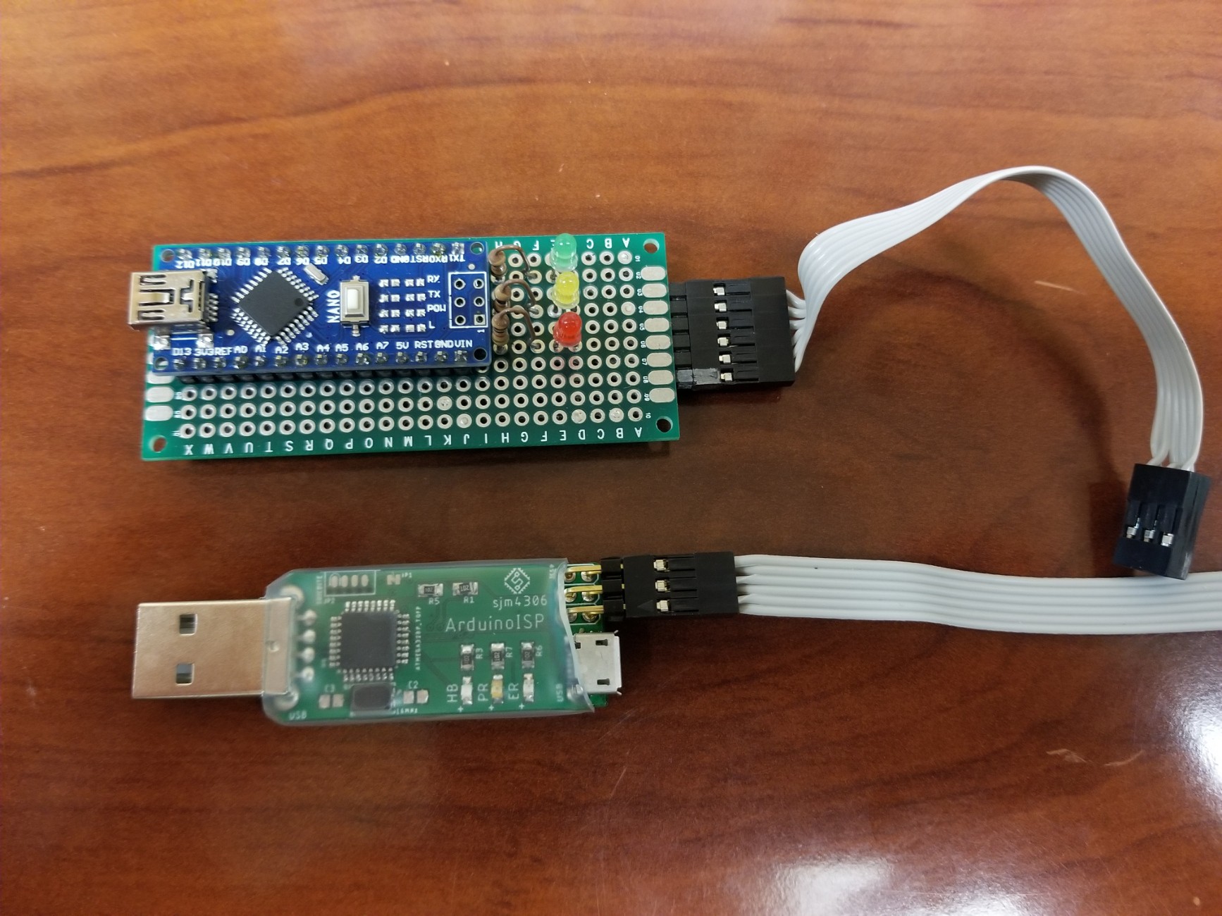
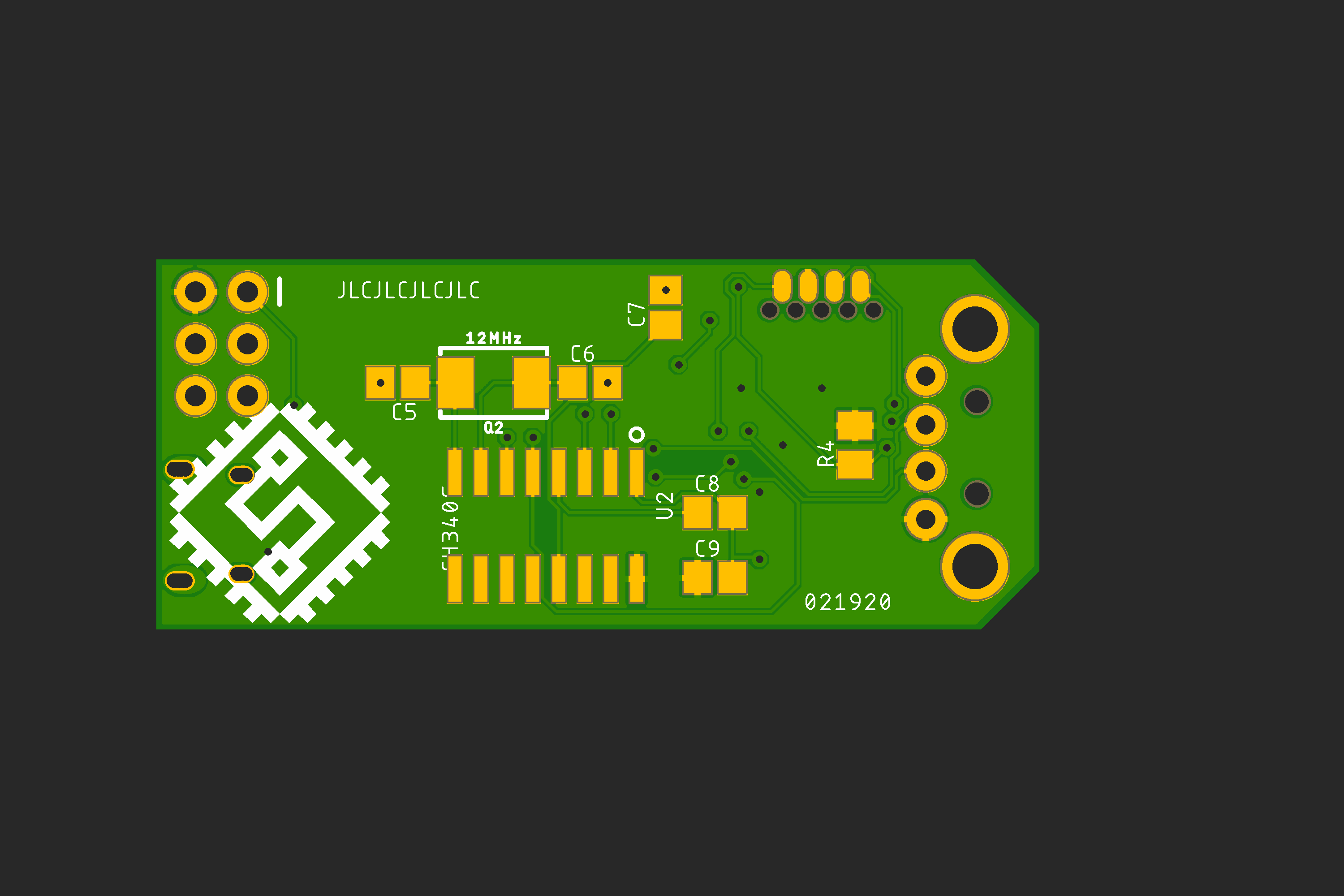
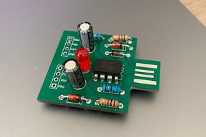
• Design, Features, Assembly and Demo

    sjm430603/02/2020 at 16:19 0 comments

    Special Thanks to JLCPCB for providing pcbs to get the ball rolling on this project. JLCPCB Prototype for $2 (Any Color): https://jlcpcb.com

    This is my current ATMEGA USB programmer (the top one):

    I built it a good six or so years ago on some perf board using a cheap Arduino mini clone burned with the ArduinoISP sketch that's included with every Arduino IDE installation. It's pretty ugly with all the point to point soldering but has worked reliably for years. It's not the most convenient though as it requires a usb mini cable, it's pretty large and can sometimes be a bit unweildy. So I wanted to basically take all the same components and shrink everything down to a tiny keychain sized programmer.

    So I started by drawing up a schematic based roughly on how the Arduino mini is configured and how it is wired for the ISP sketch:

    A few key goals for the design:

    - Include both a full size male usb connector and a micro female port so I can plug it into a computer either way

    - Roughly fit into a size that's nearly as small as just the Arduino mini board

    - Keep highly visible color coded indicator LEDs

    - Use the standard 6 pin ICSP 0.1" header so I can easily make double ended cables for easy replacement

    - Use a cheap USB to serial chip, the CH340G

    This is the board that I came up with:

    Additional features I've added are Simon Merret's awesome SOICbite programming interface (https://hackaday.io/project/165917-soicbite-programmingdebug-connector-footprint) to flash the ISP software onto the onboard ATMEGA328P, and a cuttable jumper, JP1, to prevent accidentally erasing the programmer firmware over usb after the initial flash.

    Assembly went quick, I've made a video here showing that and generally describing the firmware flashing process (my soic clip hasn't arrived yet so I had to do a rather medieval workaround) as well as demoing programming one of my other project boards.

    So that's pretty much it for now, I'll happily be using this guy for a few years hopefully. I've found that 1-1.5" clear heatshrik fits perfectly over the board protecting from shorts while allowing easy view of the onboard LED indicators. For the next iteration I will definitely space the female micro usb connector farther from the right angle 6 pin 0.1" icsp header though as having both plugged in can be a bit of a tight fit depending on the girth of the usb cable used. Additionally, moving to the newer SOIC-8 CH340N that doesn't require any external 12MHz crystal will make the design even easier and cheaper.