 kmatch98
Bill of Materials
- M2 bolts - 10 mm (4 quantity)
- M2 nuts (4 quantity)
- 3D printed case (2 pieces)
- 1.3” IPS TFT (generic version used here, 7789 chipset)
- Adafruit Itsy Bitsy M4 Express (https://www.adafruit.com/product/3800)
- Adafruit DS3231 breakout (https://www.adafruit.com/product/3013)
- CR1220 Battery (https://www.adafruit.com/product/380)
Wiring Instructions
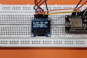
The following table shows the wiring instructions for the Itsy Bitsy, the TFT display and the DS3231 real-time clock breakout. The wiring color indicates the wire insulation color that is shown in the images.
|
Adafruit Itsy Bitsy M4 |
TFT Display |
DS3231 Breakout |
My wiring color |
|
M0 |
SDA |
yellow |
|
|
SCK |
SCL |
blue |
|
|
3V |
VCC |
VCC |
red |
|
GND |
GND |
GND |
green |
|
SCL |
SCL |
black |
|
|
SDA |
SDA |
white |
|
|
10 |
DC |
white |
|
|
11 |
RES |
black |
|
|
13 |
BLK (backlight - PWM signal) |
yellow |
Special notes on the software (Arduino)
Be sure to include the images.h file into your Arduino project.
The generic IPS TFT display I used has a ST7789 chip, and it required to use "SPI_MODE3" in the tft.init statement.
I control the backlight brightness by a PWM signal. I selected a value of 8 since this is a bedside clock. Also, you can change the minute hand to a different color. White can be very bright at full brightness (255).
I updated the software to includes the hooks for daylight savings time using the Timezone library (https://github.com/JChristensen/Timezone). Before compiling, update the Timezone rules for your location.
Also, I am including a short program to update the real-time clock to the current time. Run this to update the RTC before you load the final program. This short code allows you to update the real-time clock to UTC time by providing a few variables so you can create the correct time offsets.
3D Printing the case
The case is relatively easy to print. I printed the front standing upright, with support. I printed the back piece with the back lying flat on the print bed.
 UTSOURCE
 Mark Jeronimus
 brett.oliver
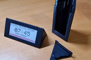
 Aaron Christophel