 Michael Gardi
With all preparations complete I forged ahead and built the bottom part of the H-500.
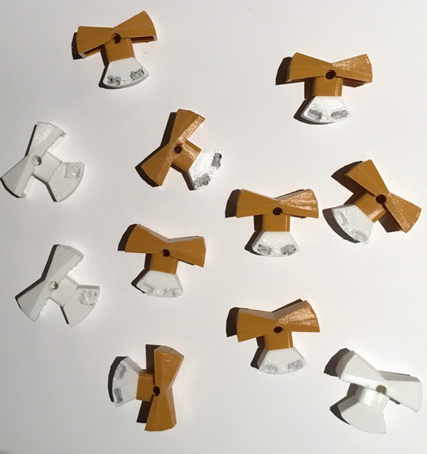
Here is what I did. I started by preparing the eleven rocker switches required, three momentary "spring" return types for the H-500 pulse switches, and eight ON-ON variants for the input switches. I took care and made sure that the magnets were all oriented the same way and used my 3D pen to secure them in place. See Rocker Man for details.
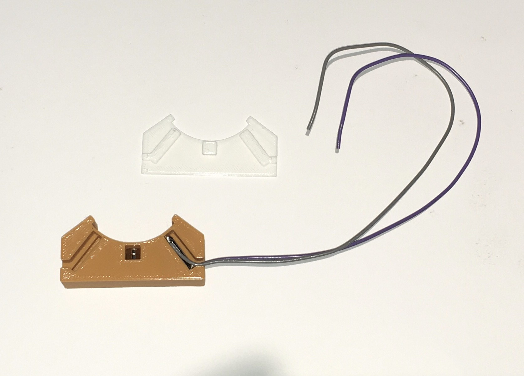
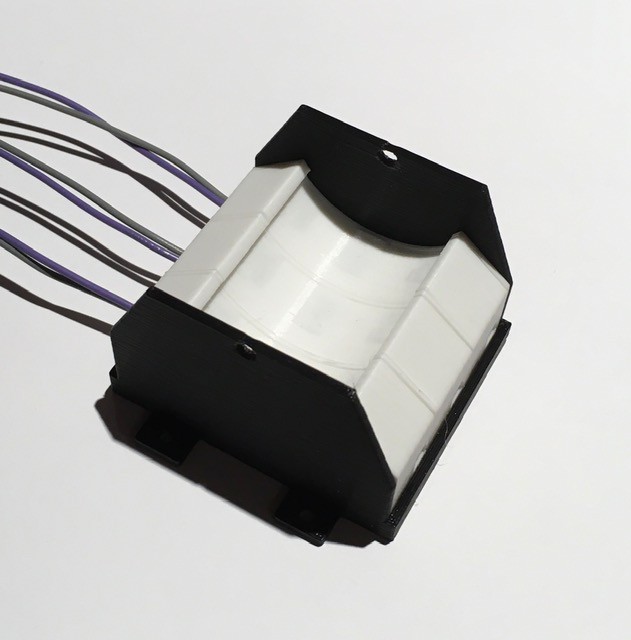
Next I prepared the eleven rocker switch bases. They are all the same as the one below. You will notice that there is only a single reed switch. I had already decided that I would use an Arduino to manage the clock and pulse signals (reading the clock rate, generating the clock signals, debouncing the pulse switches, etc., more on this later in the project) so I thought I would take advantage and generate the input switch signals based on a single reed per switch knocking about $20 off the BOM. Also I'm not sure what the final assembled layout will be so I attached extra long leads.
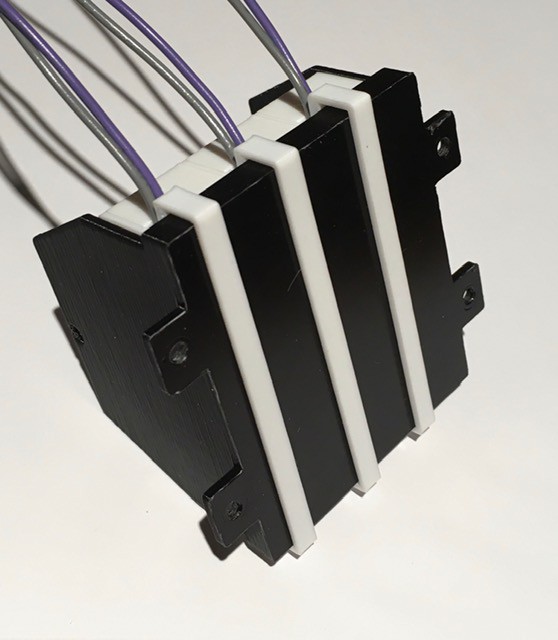
I designed two "cradles" to hold the switch bases.
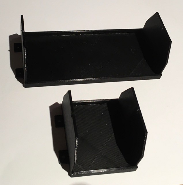
The bases slide in snugly.
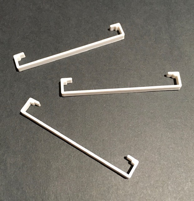
I made some simple clips to hold the base pieces securely in place.
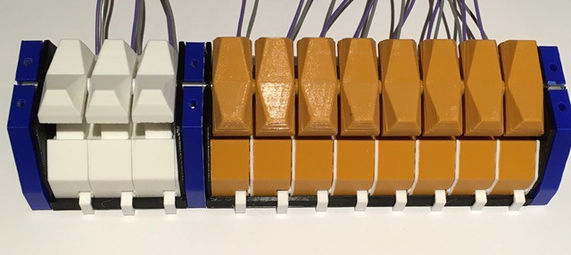
Same for the eight switch cradle. I'm running a bit low on filament so mixing colors a bit.

Next I printed some mounting plates. They have slots for M3 nuts to ensure a strong bond.

Connected the cradles to the mounting plates with M3 x 10 bolts.
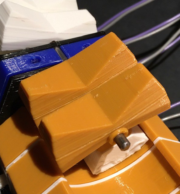
Cut a 1/8 inch steel rod to span the length of the combined switch assembly and printed some small spacers to help align the switches.
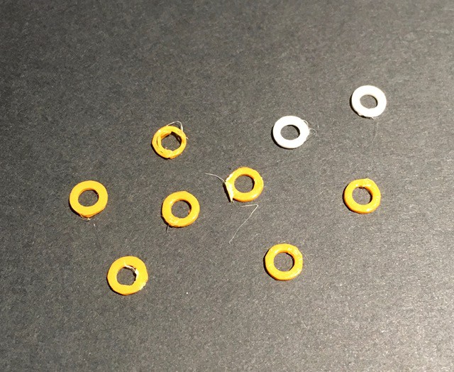
Starting from one end I began slowly sliding the rod through the pivot holes attaching the rocker switches with their counter weights as I went. Between switches I inserted one of the gaskets.
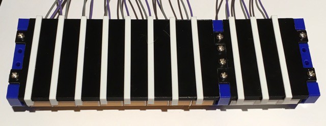
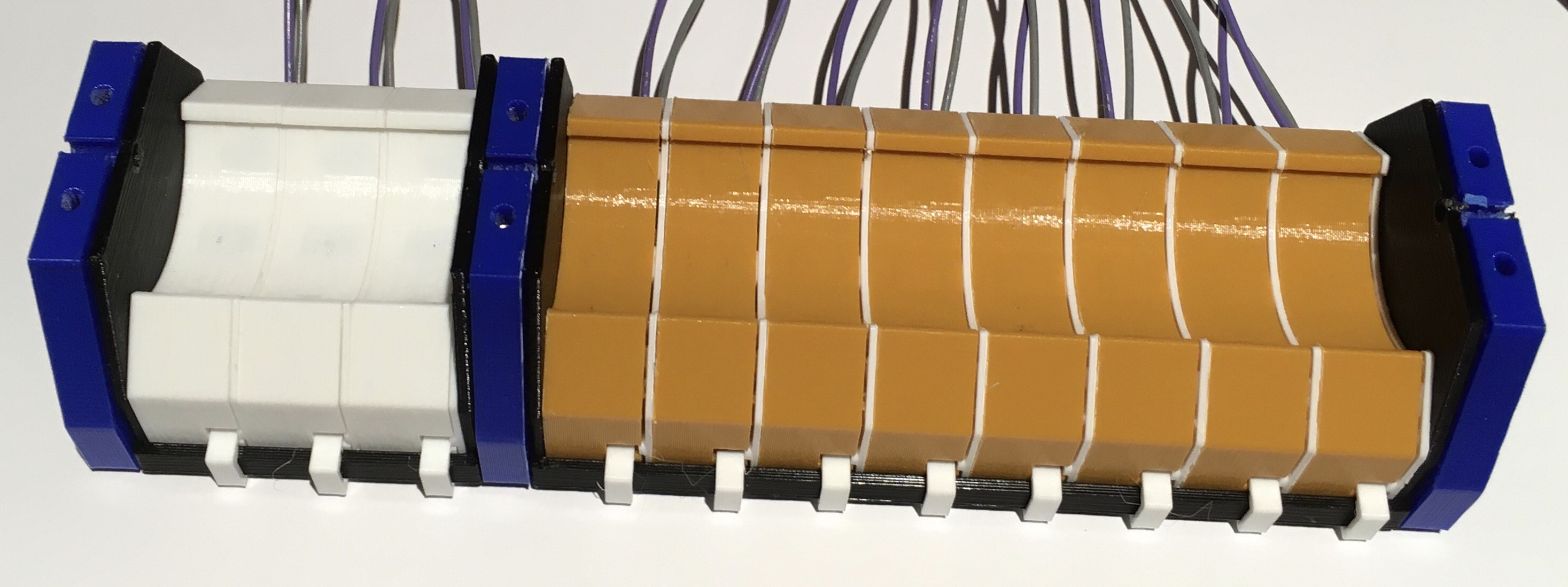
When done the switch assembly should look like this.
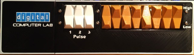
I printed the face plate for the panel (in two pieces, need a larger volume printer). I paused and changed the filament color multiple times to print the text and the logo. All that's left is to attach the switch assembly to the face plate. (Or is it the other way around, the switch assembly is quite massive.)
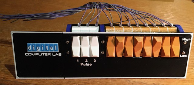
That's it. The switch panel is done. It is tweaked a bit from the original. I had to make the characters bigger by about 20% to get them "print" correctly when extruded. The switches when assembled ended up being a little wider than the originals. Since I had already printed the switches, I made the panel holes a little larger to accommodate them. When I get the chance I'll get some black steel bolts so the heads are less noticeable. All-in-all though I'm extremely happy with the result.
Discussions
Become a Hackaday.io Member
Create an account to leave a comment. Already have an account? Log In.
Thanks Tom. Ya the logo really pops (like literally as it's printed in layers ;-).
Are you sure? yes | no
Absolutely phenomenal. Who knew the DEC logo would look so perfect 3D printed?
Are you sure? yes | no