 Michael Gardi
All of the active controls for the H-500 are located in the lower part of the device.

These included (taken directly from the Computer Lab Workbook):
- Rocker Switches - Rocker switches can be used to provide either a HI or a LO logic level. If the upper side of the rocker switch is depressed, the two corresponding switch output terminals (directly in front of the switch) are taken to a HI level. If the lower side of the switch is depressed, the two corresponding output terminals are taken to a LO level.
- Pulser Switches - The outputs of the pulser switches are normally LO. When a pulser is depressed, the corresponding two terminal terminals go to a HI level. When the pulser is released its output terminals return to the LO condition. Internal circuits connected to the pulsers make sure that when a pulser is depressed or released, electrical noise generated in the switch is not transmitted to the pulser output. This special circuitry makes the pulsers useful in applications requiring noise-free transitions from one level to another. Rocker switches do not have this feature.
- Clock - The clock provides a continuous train of HI pulses. Clock pulses are 50 nanoseconds wide. The frequency of clock pulses can be continuously varied from less than one pulse per second to over 10 million pulses per second. The slowest range of the clock is obtained by connecting the common clock coarse terminal to the left-most speed-selecting terminal. The repetition rate of the clock increases with each terminal to the right. The fastest repetition rate is obtained by leaving the clock range selector disconnected. Repetition rates within each coarse range can be varied using the clock fine control. (Fully counterclockwise gives the slowest repetition rate; fully clockwise provides the fastest rate.) The clock range coarse terminals are to be used only for selection of clock repetition rate. The clock output is obtained from the two terminals labeled CLOCK OUTPUT.
- Lamp Indicators - The operation of experiments constructed on the COMPUTER LAB patchpanel is monitored by the lamp indicators. A lamp will be ON if its corresponding input is at a HI logic level. A lamp will be OFF if its corresponding input is at a LO logic level. If no connection is provided to a lamp, the lamp will be OFF. Lamps will respond to sustained logic levels and pulses of sufficient duration to activate the lamp filament.
So how were these functions implemented back in the late 60's. Like this:
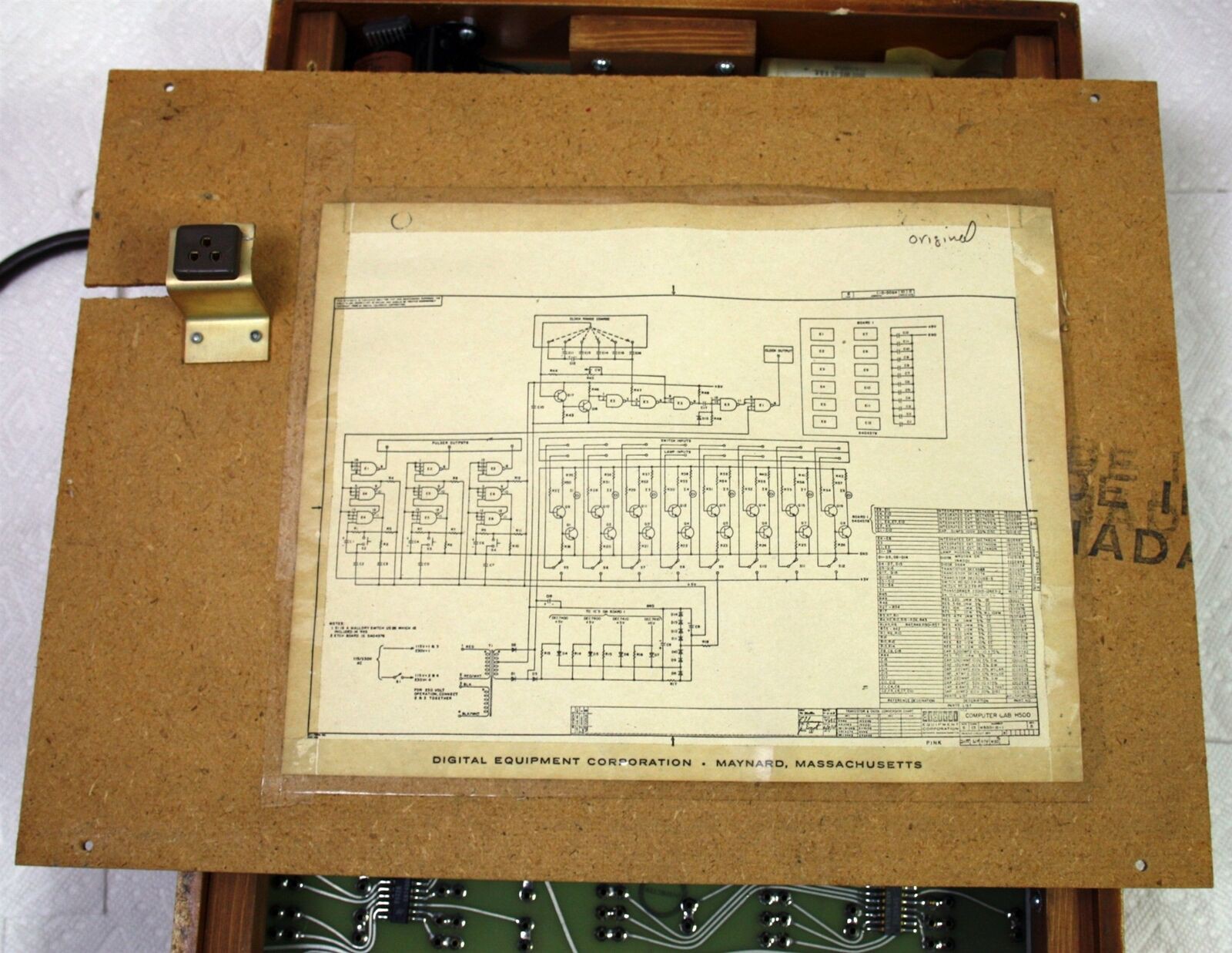
I apologize for the image quality. I'm trying to find a better photo. Looks like this schematic was taped to the back of the frame's rear cover.
Now I'm not going to pretend that I completely understand all of what is going on in this schematic. Electronics is not my strong suit, I'm more of a digital guy. (if anyone wants to help me out here with a short description of what the above circuit does I would be happy to include it in the write-up.) Suffice it to say that the complexity of reproducing this circuit goes counter to two of my primary design goals with this project: make it easy to reproduce and not too expensive.
Fortunately I do know what the circuit is supposed to do. So what would be an easy and cheap replacement, well understood by today's community of makers, well an Arduino of course. This is what I came up with:
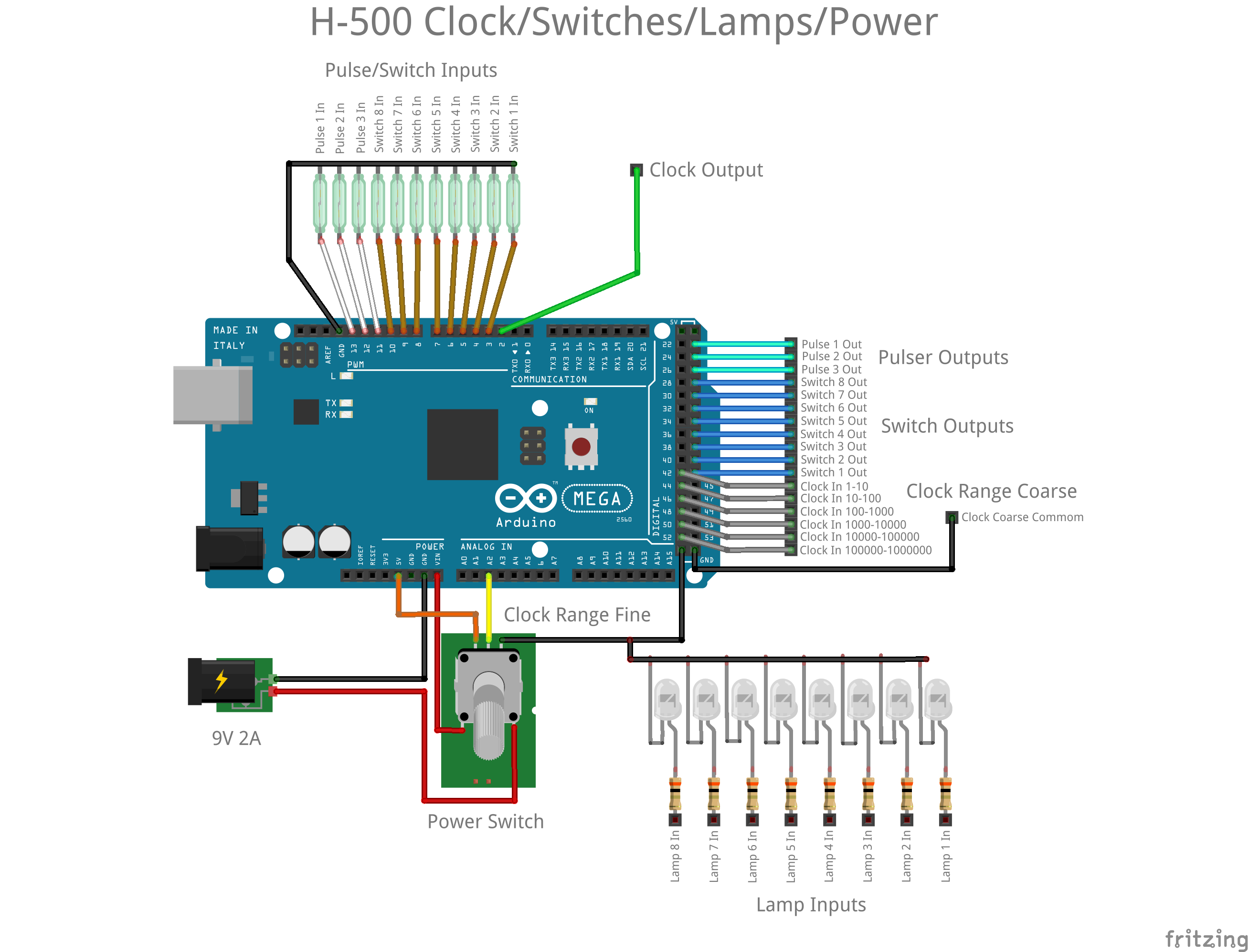
Rocker and Pulser Switches - The magnetic reeds of the rocker and pulse switches are monitored by eleven inputs that are set with their pull-ups enabled. When the normally open reed switch is "activated" by a magnet its input line will be pulled down. The Arduino sketch monitors changes to the reed switches and will only change the state of it's corresponding output line once the switch has been suitably debounced (three consecutive reads 20 milliseconds apart with the same state). In this implementation all switches are debounced, not just the pulsers. We are already at 22 I/O lines so it's a good thing that the Arduino I had lying around was a MEGA 2560.
Clock - Six more inputs with pull-ups enabled were dedicated to monitoring the clock range coarse jumpers. The clock frequency ranges that each enables can be seen on the diagram above. Ranges are checked from lowest to highest, stopping at the first one found to be enabled with a jumper. Also the potentiometer is read via an analog in line and converted to ten steps (1-10) and applied as a multiplier to the lowest value in the selected range. So if the clock range set is 10-100, as the potentiometer is turned clockwise, the clock frequencies will be changed to 10, 20, 30, ..., 100 clocks per second. If no coarse range jumper is set, I leave the clock frequency fixed at one clock per second. Clock pulses are emitted via a digital output line.
Lamp Indicators - Included in this diagram for completeness, the lamp inputs are not processed by the Arduino in any way. Just apply a Hi signal and they will turn on.
Power - A switched potentiometer is used to turn the device on and off as with the original.
Using an Arduino is not without some compromises. First of all I'm using the excellent TimerOne library to implement interrupt driven clock pulses. It tops out at about 1,000,000 interrupts per second, so that's my maximum frequency as well, 1,000,000 clocks per second. On a similar note the clock pulse itself is generated using the digitalWriteFast library. Within the clock interrupt the code is simply:
digitalWriteFast(2, HIGH);
digitakWriteFast(2, LOW);
According to the documentation the digitalWriteFast() "call" takes about 125 nanoseconds to execute. So that means that the clock duration will be somewhere between 125 and 250 nanoseconds. (I'll know more precisely when I can get back into my maker space (kwartzlab) and access a scope.) A little more than the 50 nanosecond duration the original could produce, but I think it will be adequate for my purposes.
I know that I will probably get some feedback for using a "microprocessor" in this project. If were trying for a more authentic replica I would totally agree. However in this case, where I and am shooting for more of an H-500 Computer Lab working reproduction, the Arduino allows me to simply replace a bunch of discrete components with a cheaper, faster (at least for me), easier, better understood solution.
I've added my Arduino sketch to the Files section of this project. It's not pretty but gets the job done.
Discussions
Become a Hackaday.io Member
Create an account to leave a comment. Already have an account? Log In.