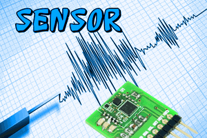
This sensor will easily detect the distortion of sheet of steel or glass it is attached to.
What's novel is the extreme simplicity of design thanks to the high sensitivity of the piezo element used as the sensing element. Otherwise a mechanical strain sensor would otherwise be done with a Strain Guage which produces a tiny resistance change according to mechanical deformation which requires careful amplification at microvolt levels.
A piezo sensor instead has a much lower part count. In contrast to a conventional resistive strain sensor which outputs a stable signal, the piezo generates a transient signal.
The microcontroller senses the piezo voltage with its ADC. If the voltage exceeds a set threshold the microcontroller sends alarm messages through a bi-directional serial interface (BusIO), a 16 bit length message. The trigger threshold is programmable through the same BusIO serial interface. Up to 15 sensors may share the same bus.
The bidirectional serial interface is mentioned in my other project "BusIO". It has some similarities with I2C in its operation but it allows the connection of standard RS232 (TTL levels) interfaces to simplify project development and debugging. A completely standard terminal program may be used to create a BusIO environment for monitor BusIO communications and command any sensor.
The sensor operates as following:
Intialisation.
Stabilisation. The peizo is directly connected to a AtoD input. The peizo is effectively a capacitor referenced to ground and can retain its charge for a considerable time. To ensure input always operates within ADC range the microcontroller stabilises the voltage on the piezo disc at 50% supply voltage. This is done with another pin on the microcontroller (3-state narrow pulses via 220 K resistor) to trim the peizo voltage up or down accordingly to stabilse it at the 50% point. During aquisition of 50% point the sensor sends out raw signal level data messages on BusIO to show the stabilisation is in progress.
Standby. The sensor raw value is sampled several times per second and the last few values are kept in a buffer. No BusIO data is sent out but it listens for configuration commands. As mentioned earlier the microcontroller continually monitors the peizo voltage and fine tunes it with narrow maintanence pulses when needed. During a trigger this fine tuning is temporarily disabled.
Trigger. If the peizo voltage changes by a set threshold, an alarm condition. The last three historical raw sensor values before the trigger occured are sent out on BusIO, followed by ongoing real time raw sensor values during the alarm event. As the piezo sensor is practically limited to a length of sampling time (a few seconds to a minute) the alarm condition self cancels after sending a set number of raw sensor values. Then returns to the Stabilising.
LED FLash Function. Redundant feature. Pin 7 connected LED / resistor. Flashing activates/deactivates via a command received over BusIO.
<b>Configuration</b>
The sensor stores configuration data in the microcontroller's flash memory. BusIO address, Trig threshold, NFB control (in beta stage).
A sensor may be interrogated for raw sensor value while in standby.
By default the hardware address of an unconfigured sensor is "F" (one-of-15) this is changed with the appropriate configuration command over the BusIO interface
 Marcrbarker
 Florian Wilhelm Dirnberger
 Ryan Gass
 hIOTron
 Boris Landoni