 kmatch98
Background
This is a 3D LED matrix cylinder inspired by makeTVee and adapted for 3D printing. The concept is that the matrix grid is printed flat and rolled up into a cylinder. The LED's are installed and then the sky is the limit on what you can do!
The Inspiration - makeTVee
This cylindrical LED matrix from makeTVee is where it all started. He uses laser cut card board for the sections.
https://hackaday.io/project/162035-led-matrix-cylinder
I don't have access to a laser cutter but wanted a matrix, so I adapted his design to use 3D printing for the mechanical and ESP32-based WiFi connected Feather board (Adafruit Huzzah32) as the controller.
Bill of Materials
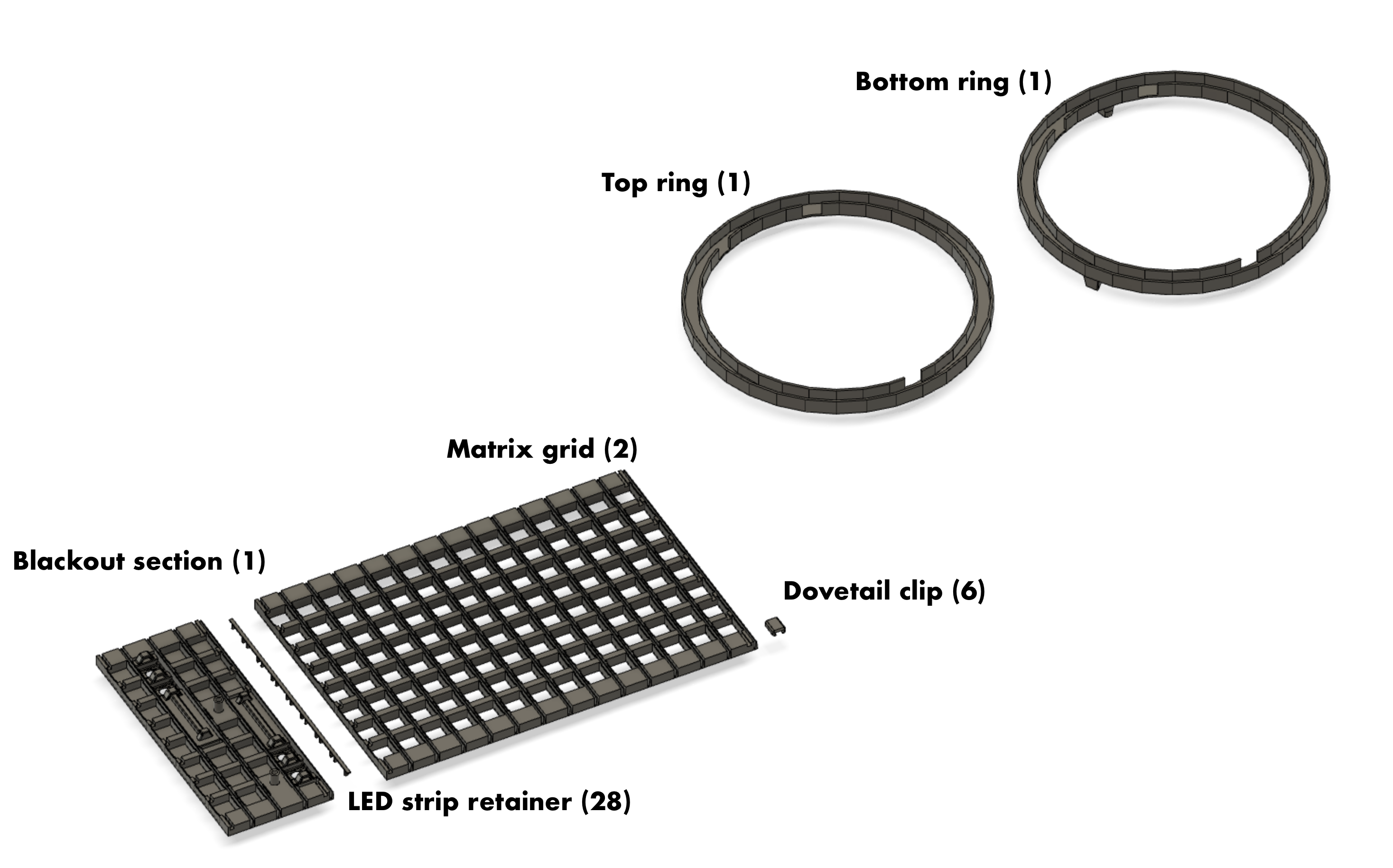
3D printed pieces
- Matrix grid (2 large pieces)
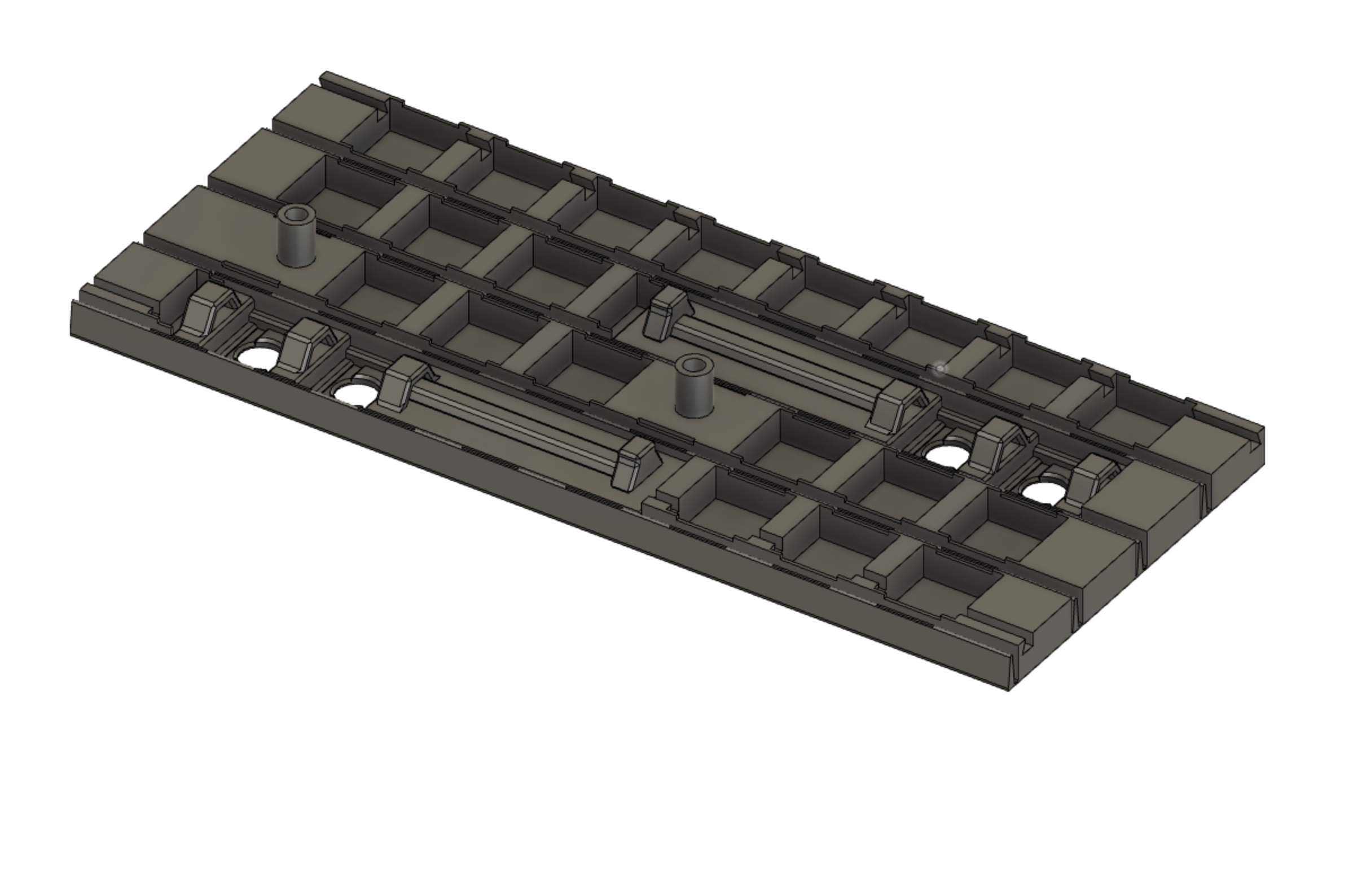
- Blackout section with four button holes and mounting location for breadboard
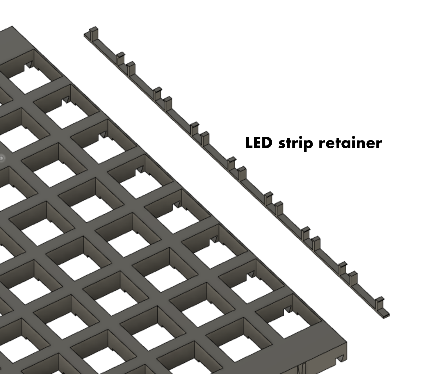
- LED strip retainers (28 quantity, probably overkill)
- Dovetail clip - Connect the sections together in dovetail slots (6 quantity)
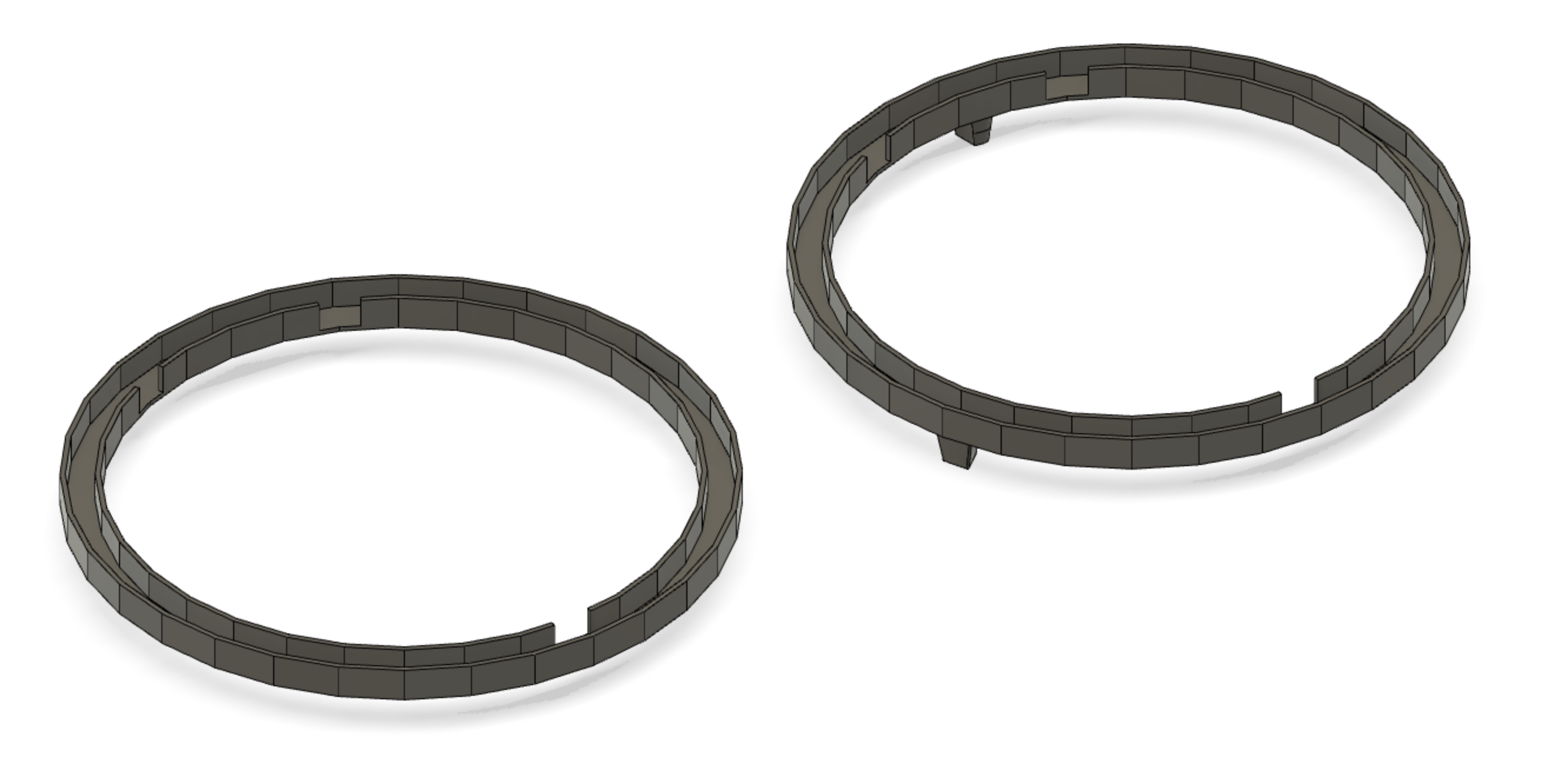
- Top ring (no feet)
- Bottom ring (with feet, or use no feet if using a wooden frame)
- (optional) Wood circle for top and bottom and a way to hold them on.
Electronics components
- WS2812 LED strip, 60 LEDs per meter, 5 meters, cut into 28 LED strips (8 quantity)
- Hookup wire
- Tactile buttons, 12mm (4 quantity)
- Adafruit Feather Huzzah32 (ESP32) - Soldered directly to protoboard or onto removable headers
- Level shifter - part number 74AHCT125 (may be optional but I used it anyway)
- 470 Ohm resistor - for connection to LED data line
- Half sized protoboard
- Miscellaneous wire, solder and flux
- 100 uF, 25V electrolytic capacitors - Across 5V USB bus and across the 3.3V (2 quantity)
- USB cable
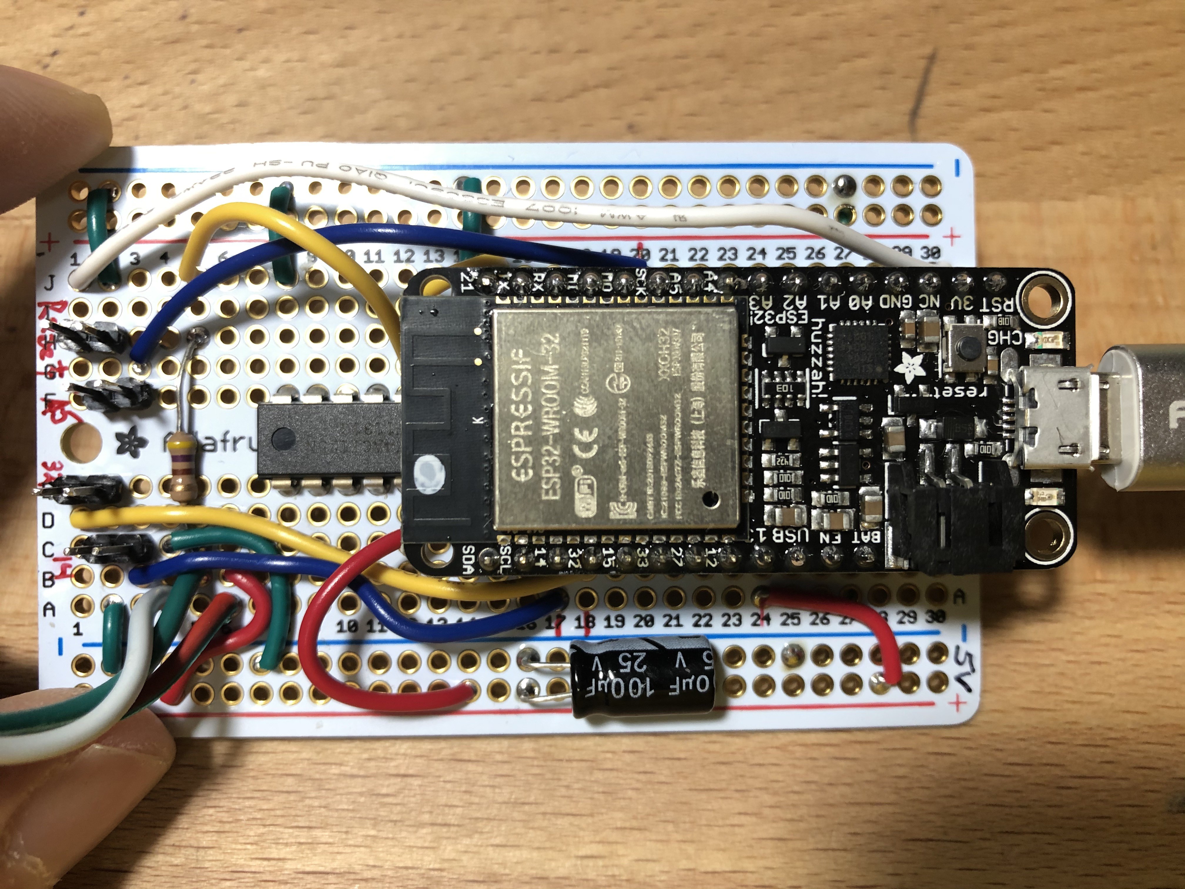
Electrical connections to the Feather Huzzah32 (ESP32)
- LED signal - Pin 21 - connects to LED strip data input through the Level Shifter
- Button A - Pin 14
- Button B - Pin 32
- Button C - Pin A5
- Reset - RESET
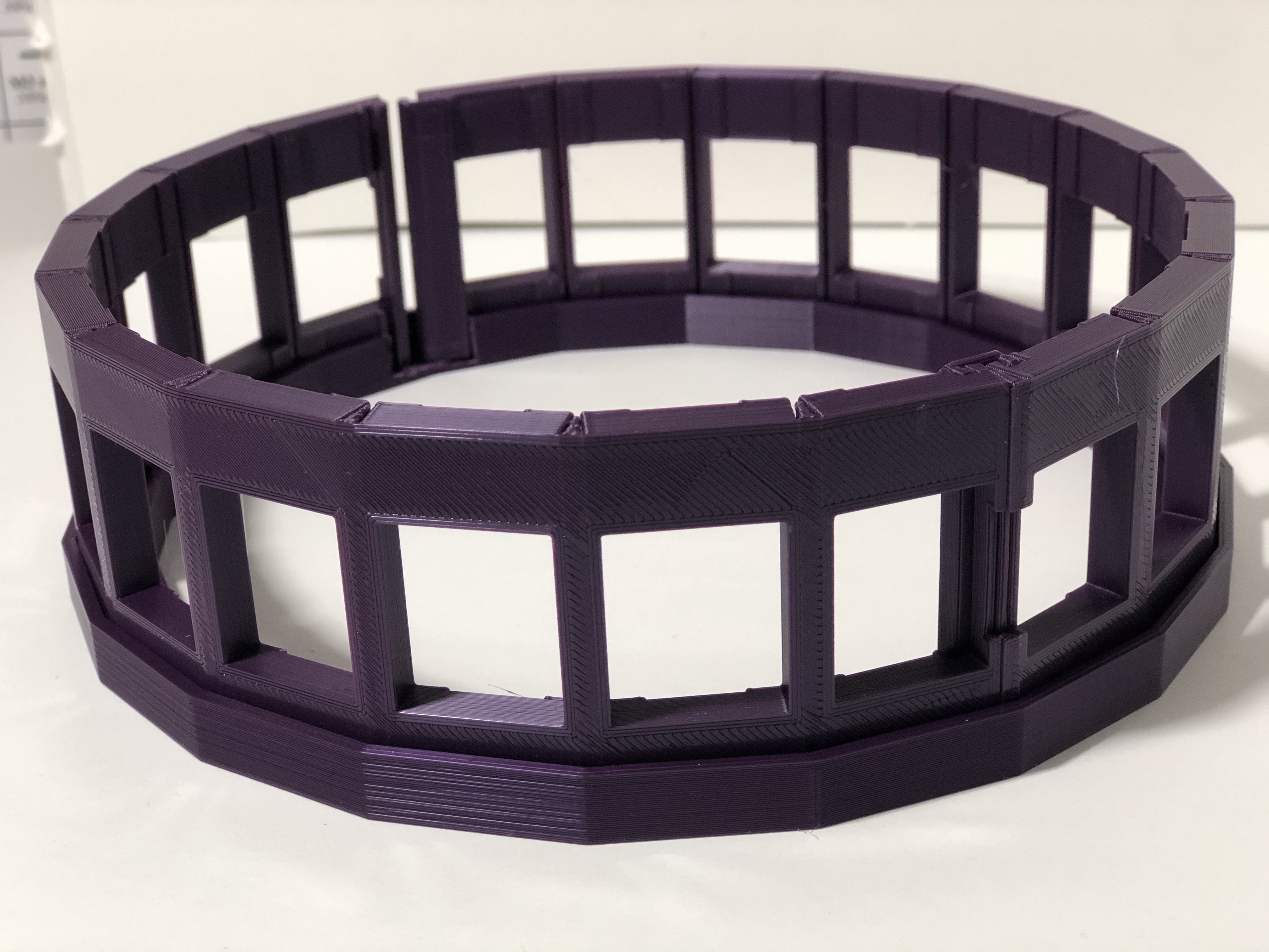
Mechanical Design - Final
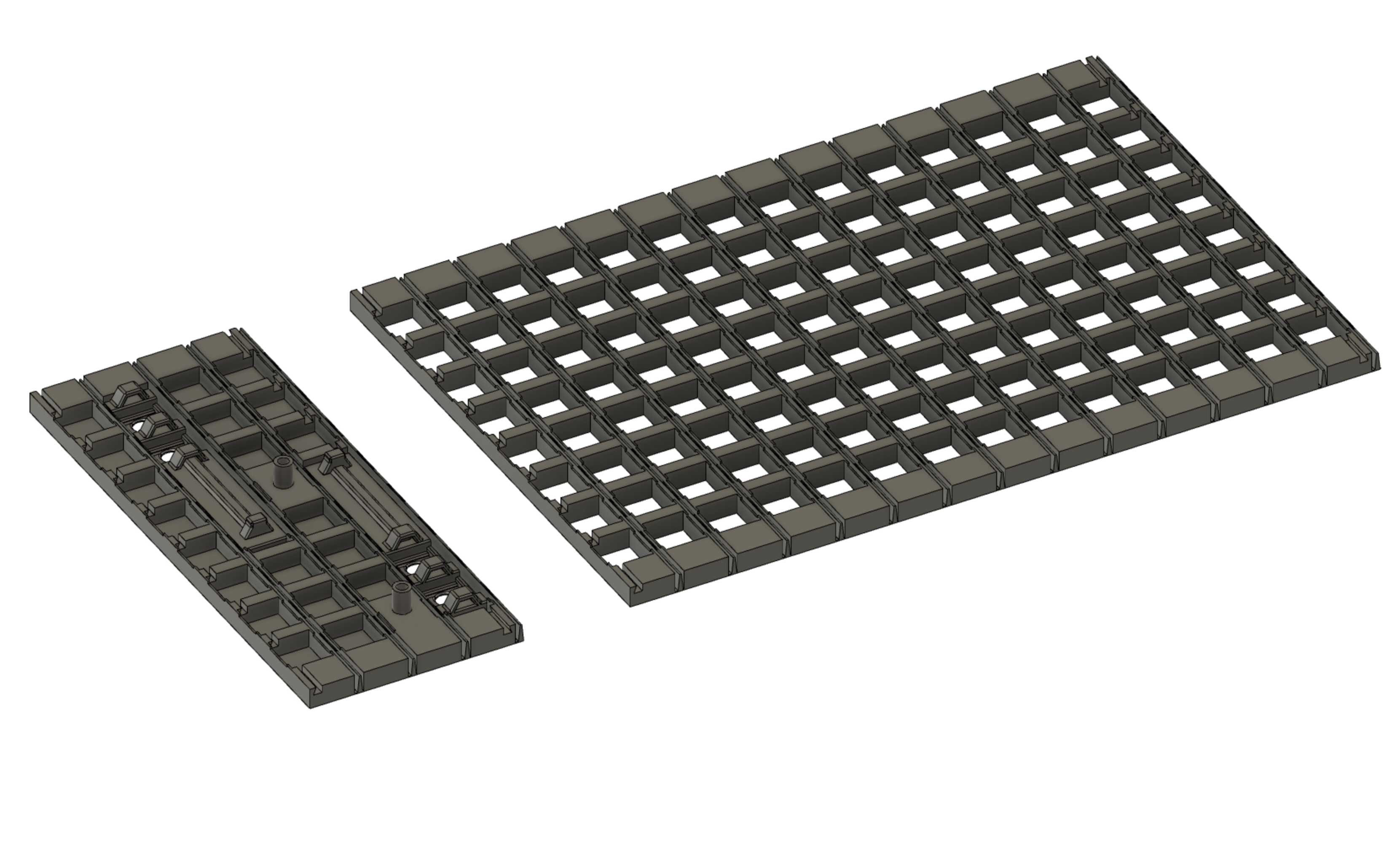
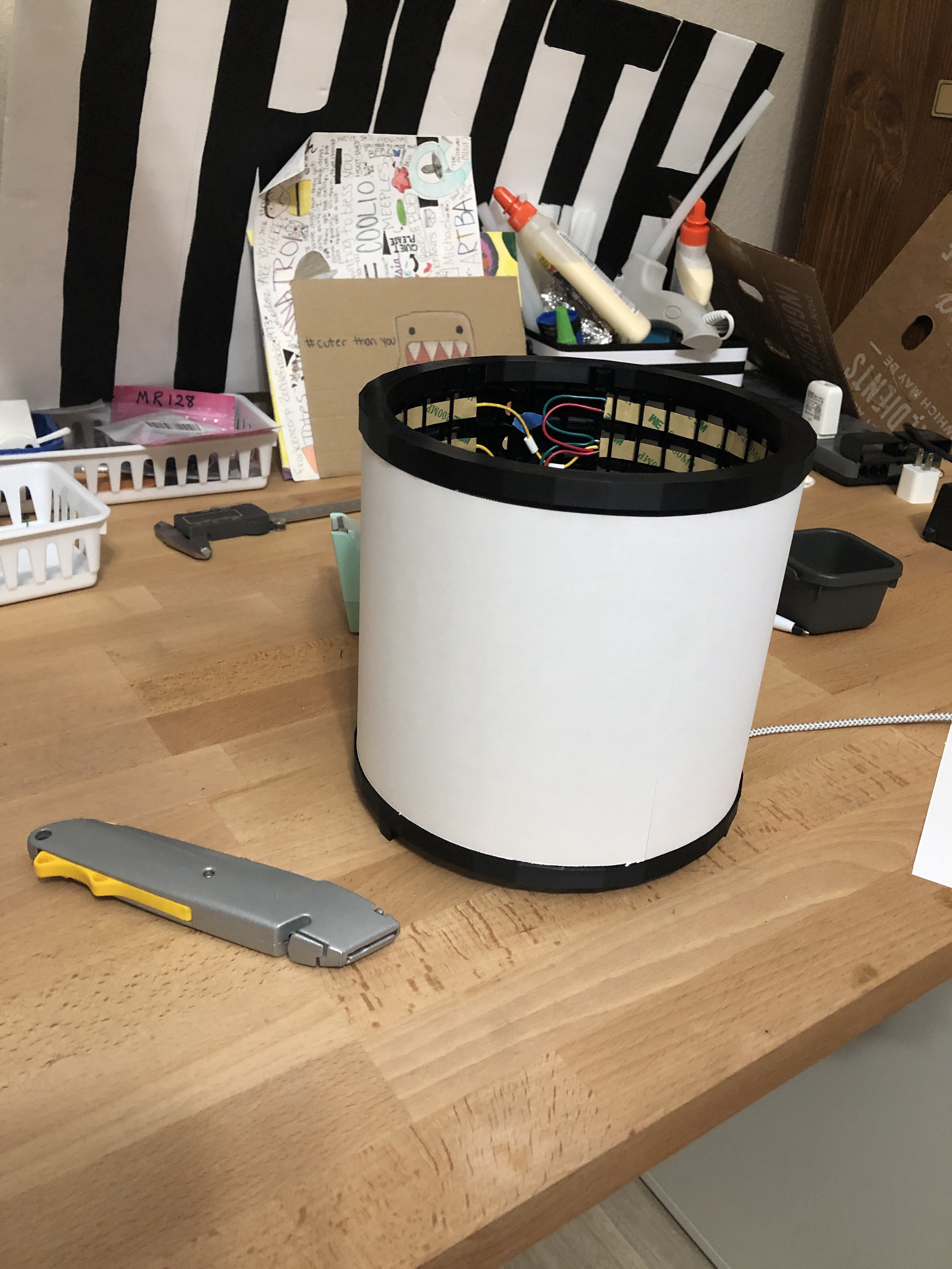
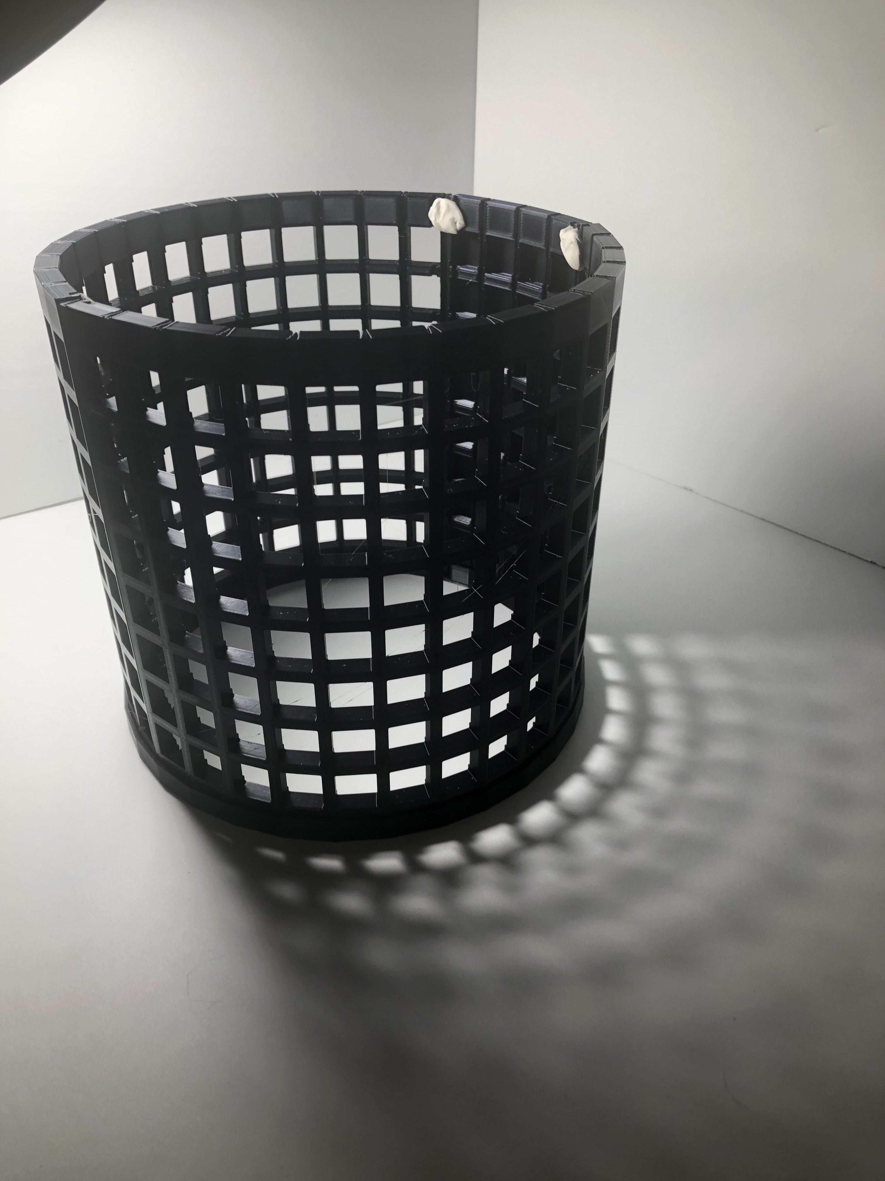
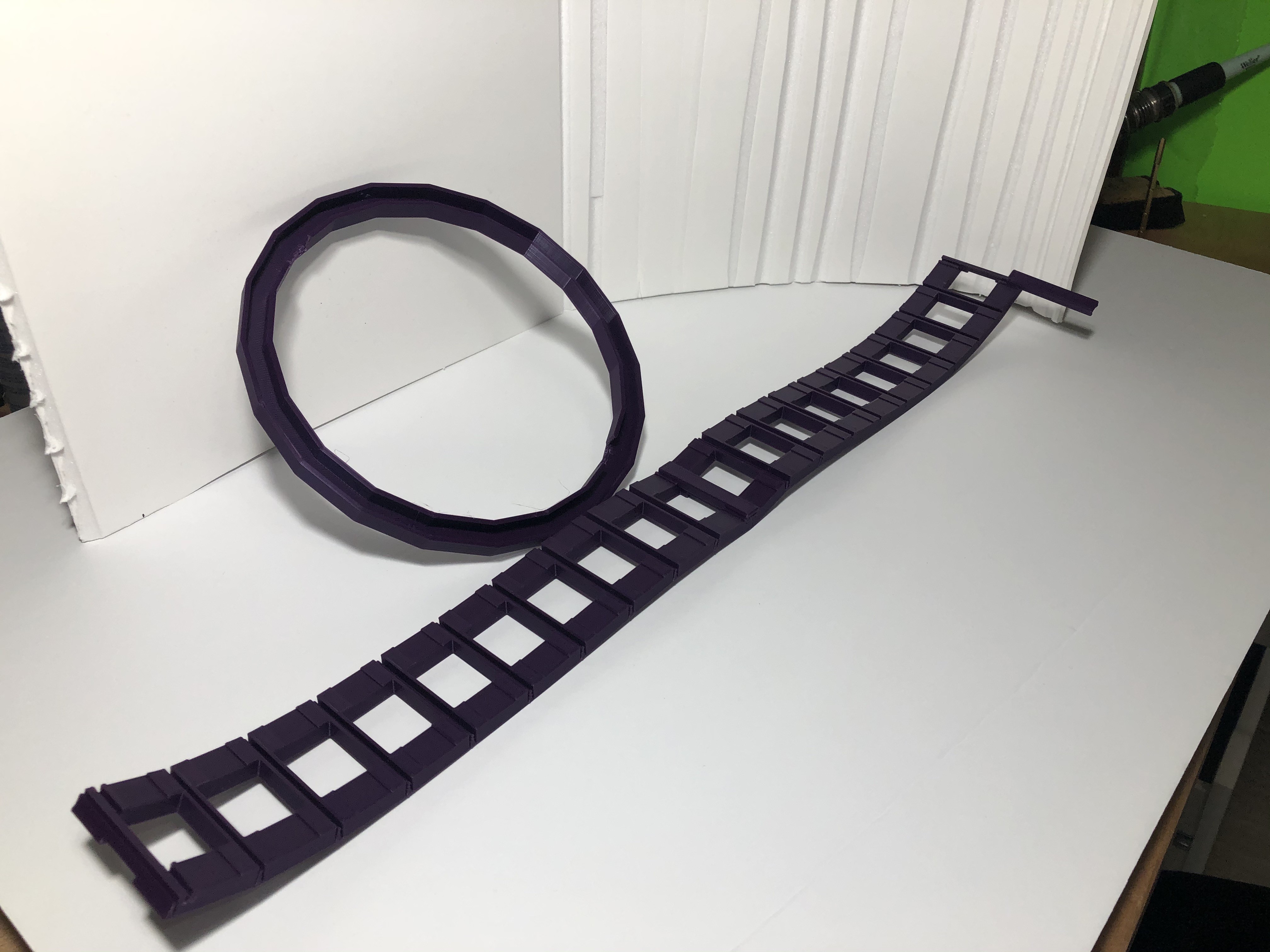
The LED matrix holder is designed to print flat on the 3D printer and then roll up into the cylindrical shape.
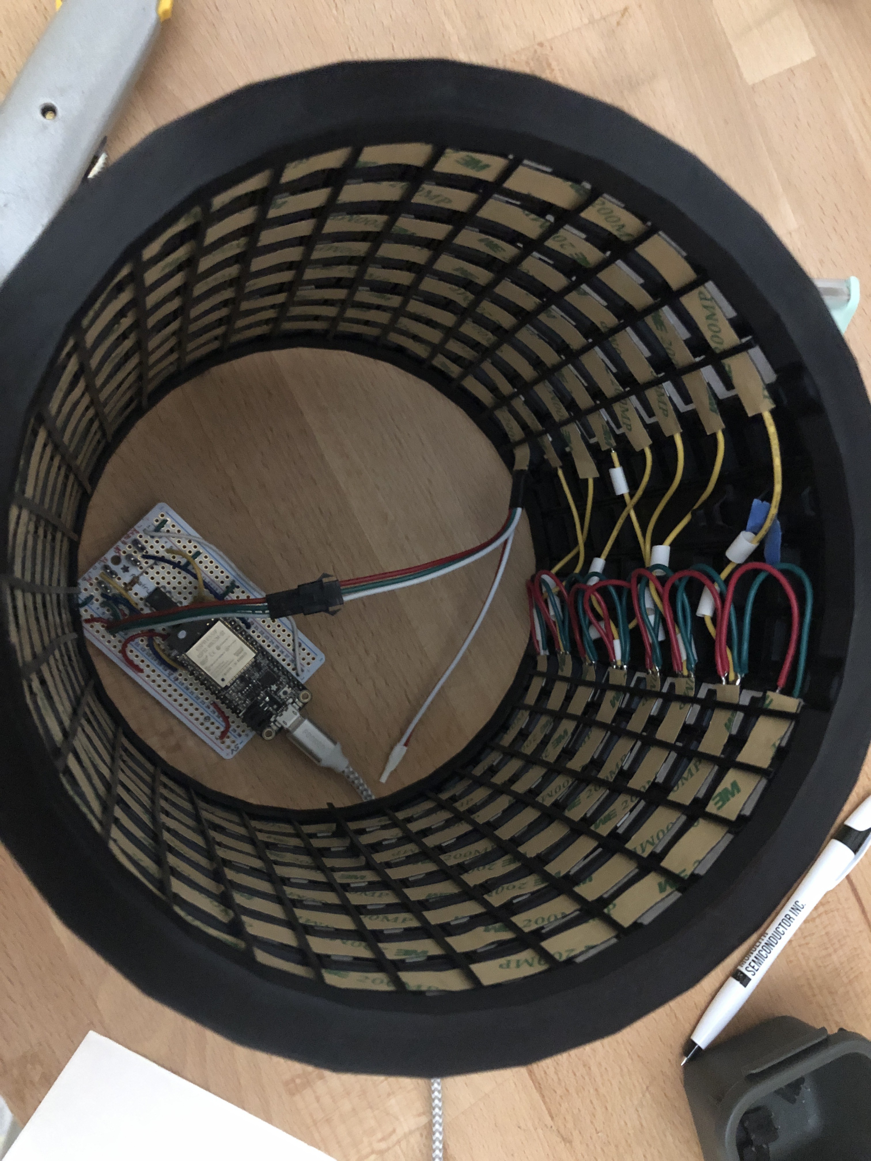
The largest panel is designed to fit onto a 12x12 inch bed (Creality CR-10S in my case). The large panel accommodates an 8x14 array of LEDs (using 60 LEDs/m strips). Two of the matrix sections are required to make the 8x28 LED array. The LED strips fit into recesses in the matrix. The LED strips run horizontal with 28 LEDs in each strip. In contrast to makeTVee, I ran my strips horizontally to reduce the number of connections as well as to simplify hiding the wiring.
A "blackout" section (8x4 worth of LED) is provided for holding the buttoms and the protoboard. So, connecting these three sections provides an effective 32 sided polygon worth of sections.
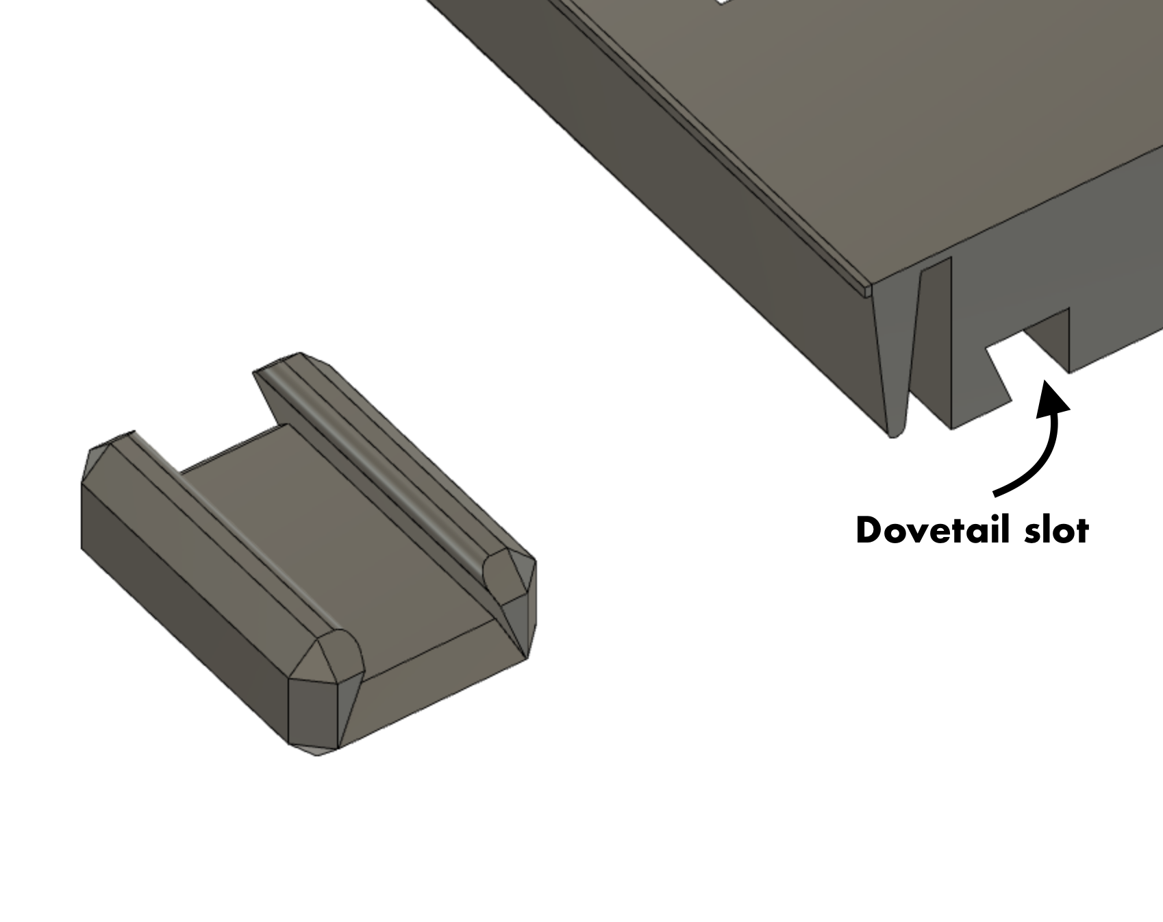
The LED matrix is completed using the LED strip retainers and the dovetail clips.

The sections are butted together and joined using the dovetail clips in the dovetail slots.
After installing the LEDs into the slots in the matrix, each of the 28 sections receives an LED strip retainer to keep the LED strip in place in its respective slot. These retainers slighly flex to maintain friction on the matrix edges.
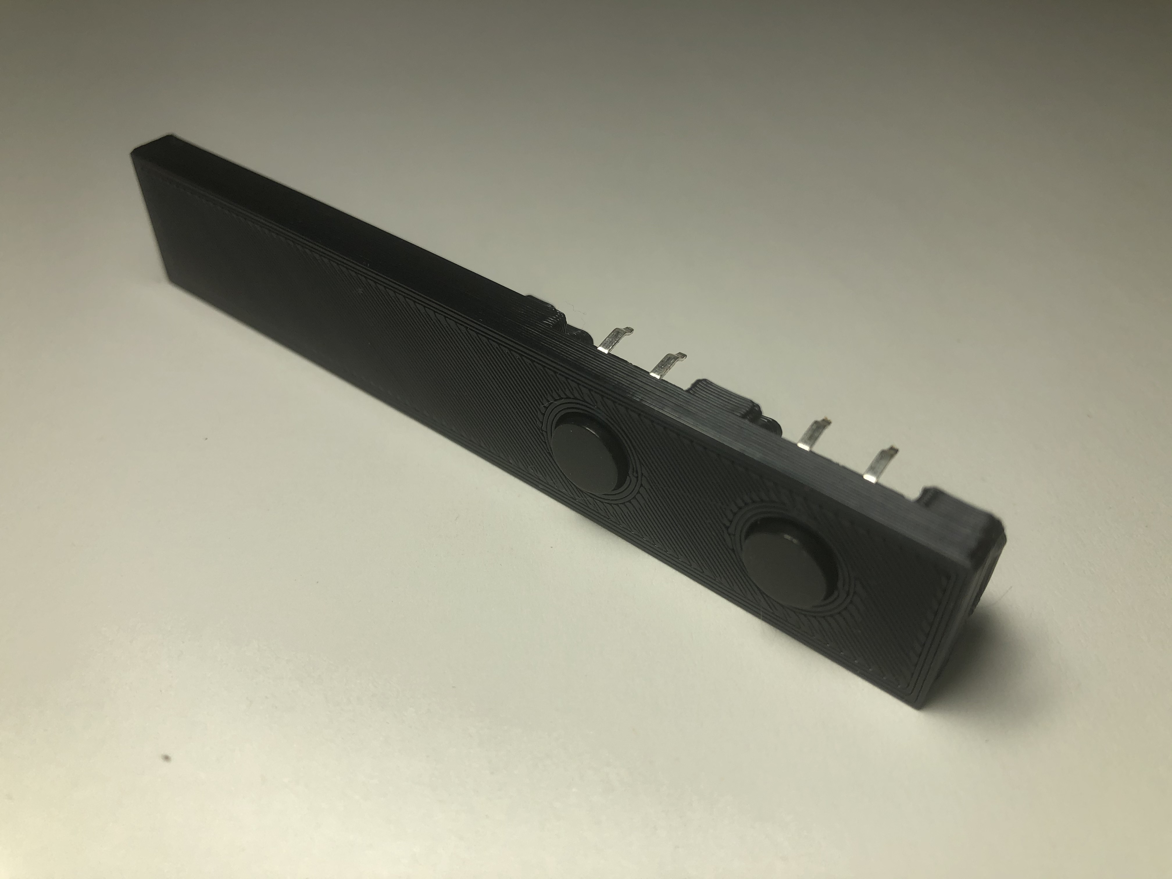
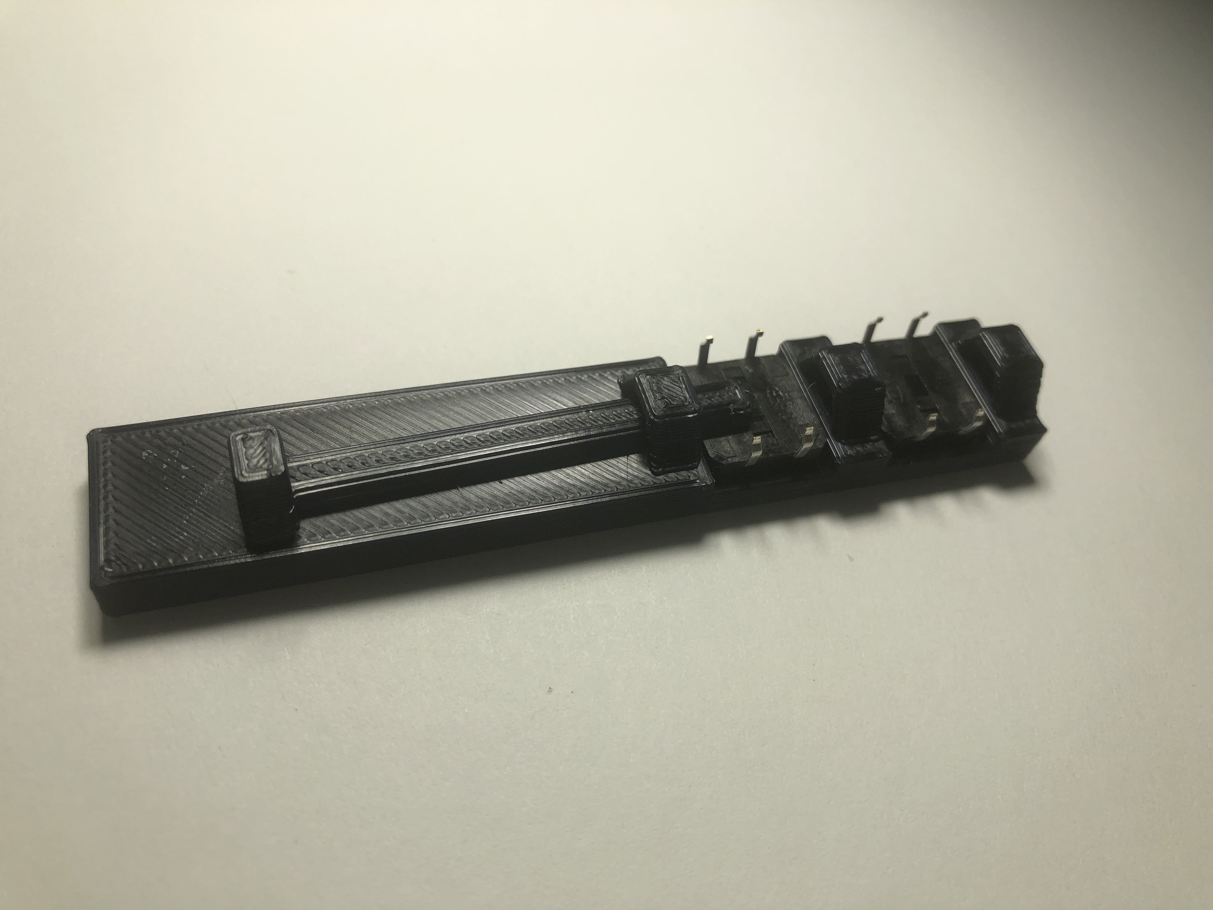
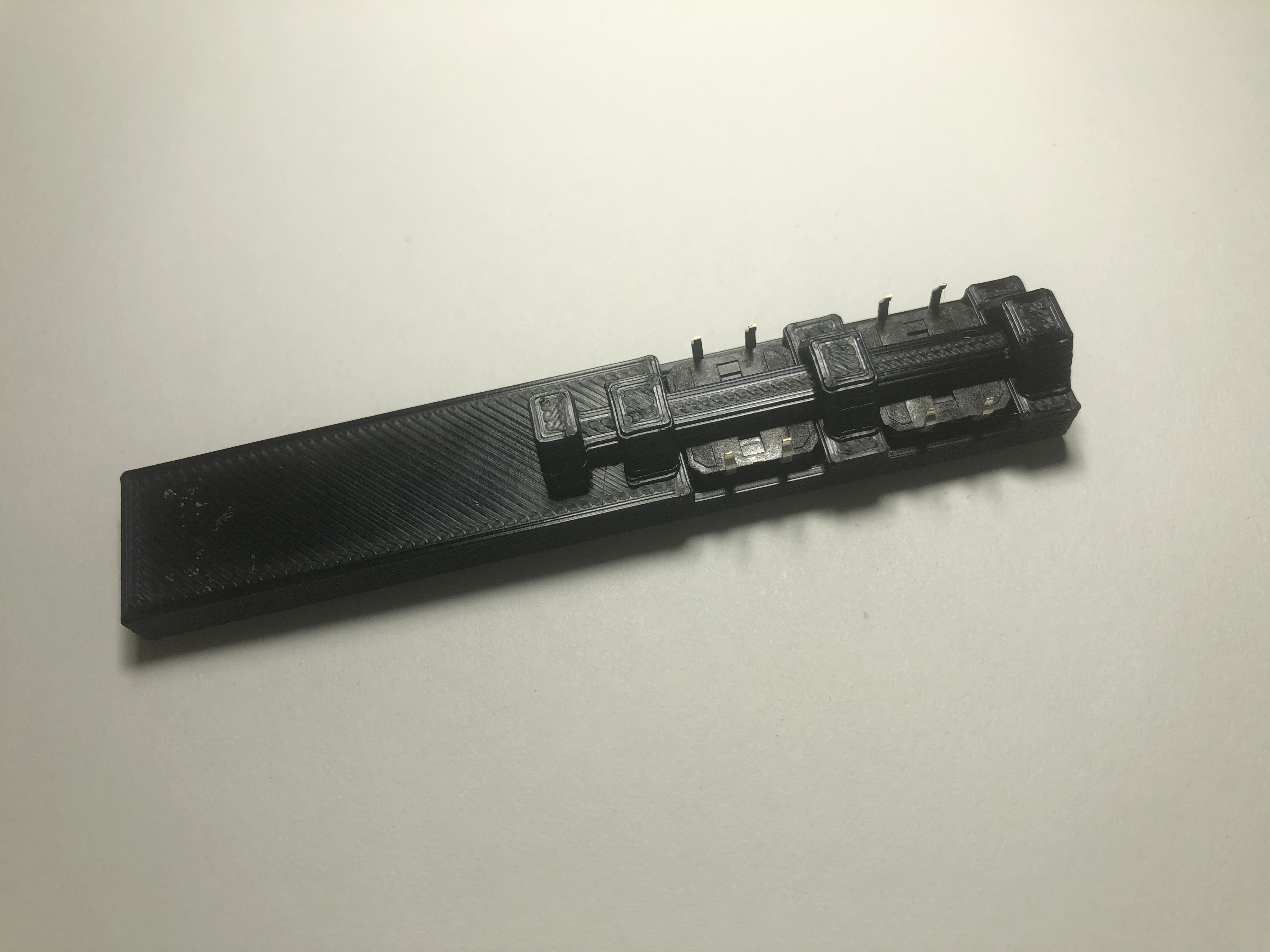
The blackout section provides room for 4 buttons and M3 bolt through holes for mounting the prototype board.
The top ring and bottom ring (with feet) have cutouts to receive the dovetail clips between the matrix sections.
Note: The USB cable snakes under the bottom ring feet and into the Feather's USB port. There's probably a cleaner way of doing this to have the USB port accessible from the blackout panel, but I didn't bother with it.
Test Program (Arduino)
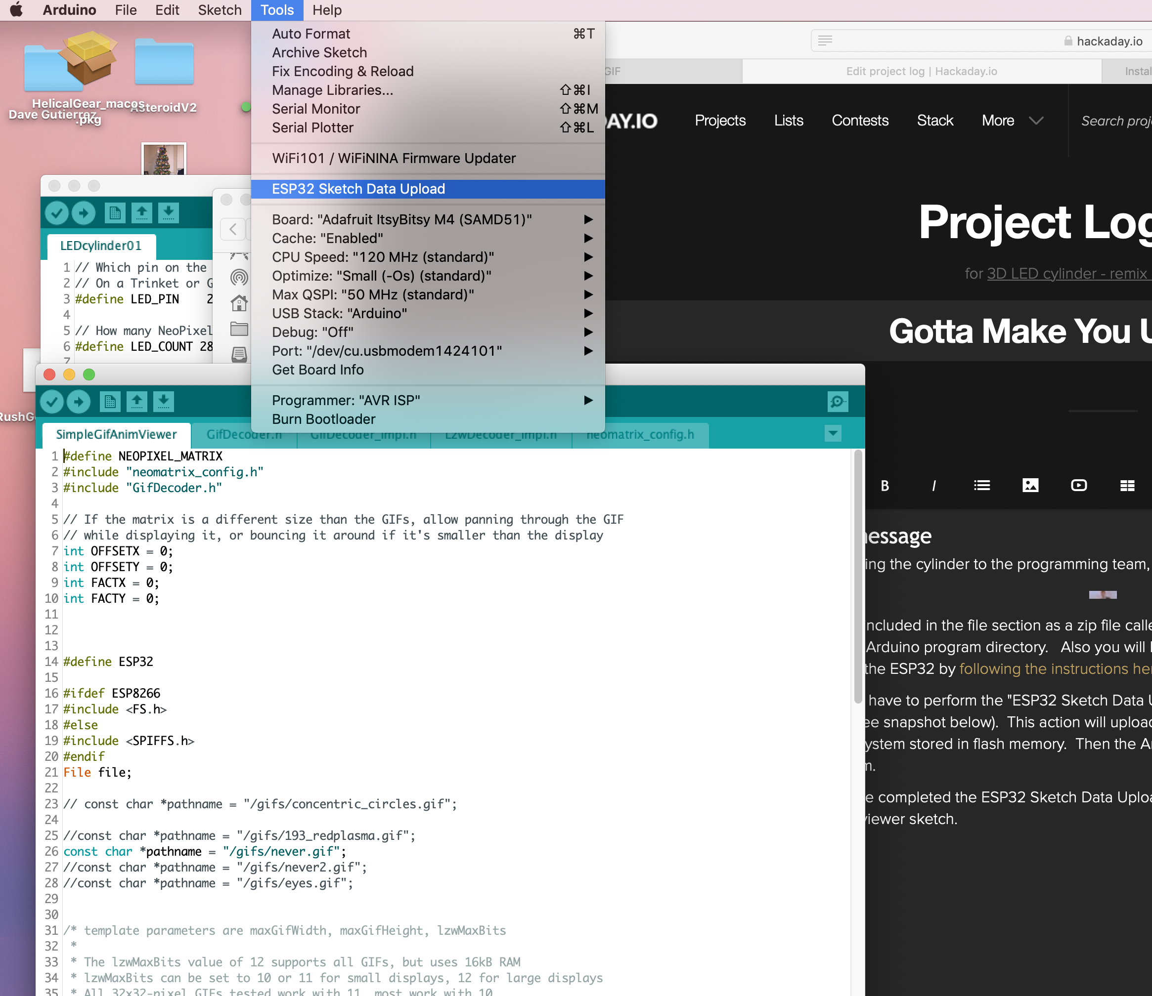
Here is a test program that shows a rainbow and then goes through red, green, blue to check out all the LEDs. Also you can check the button operation using the serial console.
This test program was based on Adafruit's NeoPixel matrix code but modified to run on the ESP32 by using the NeoPixelBrightnessBus library by Makuna....
Read more »
 Dirk-WIllem van Gulik
 kieron.gillespie
 Grant Stankaitis
This looks absolutely incrdible! I love the LED lights. - https://drivewayresurfacingwollongong/