Marcin Saj
WHAT WE NEED TO CONTROL NIXIE TUBES
- Nixie tubes required 170V DC power supply so we need Nixie Power Supply Module - any high voltage 170V converter will be fine.
- We need a driver that is suitable for high voltages - e.g. Nixie Tube Driver V2
- Any Arduino board - in this example it will be Arduino Nano
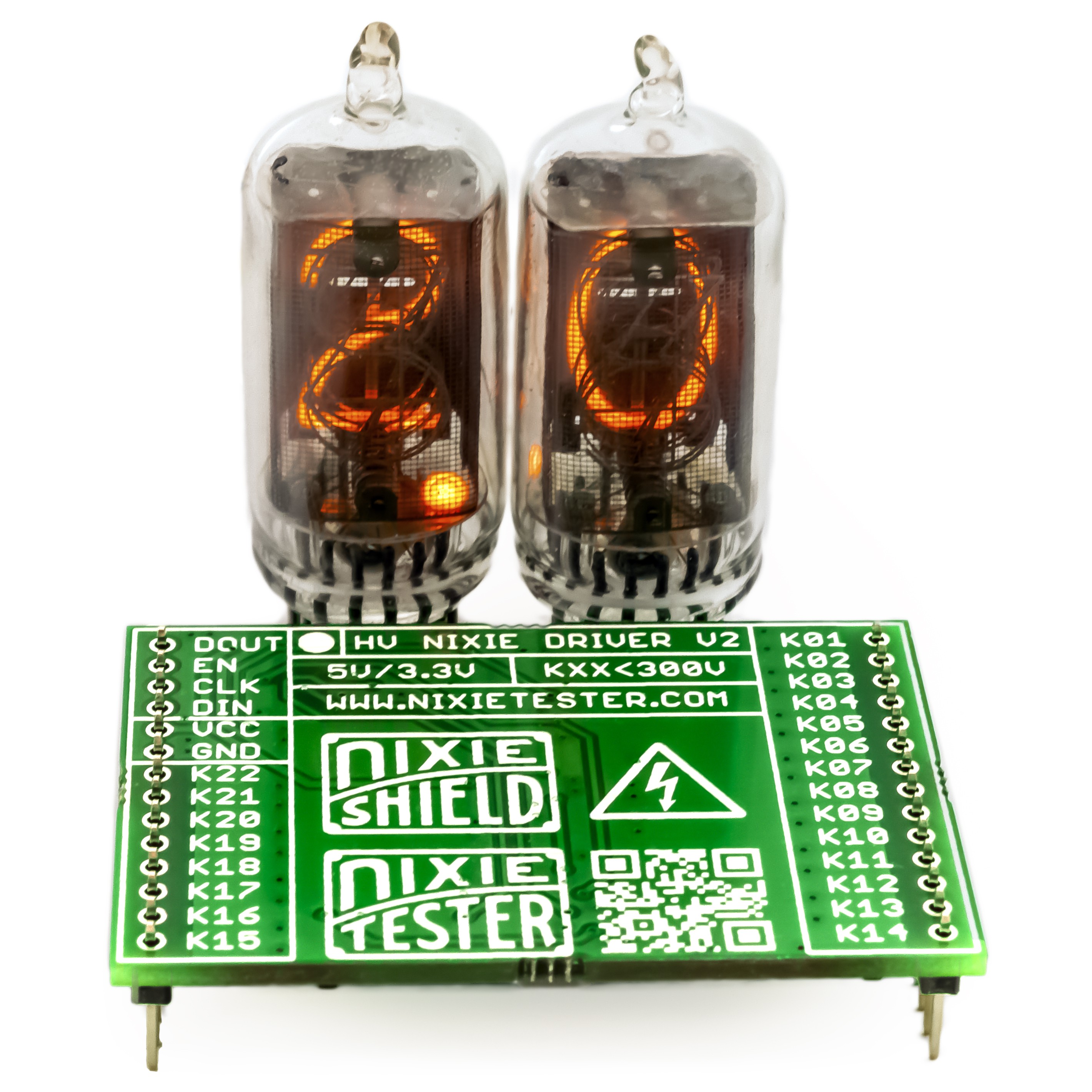
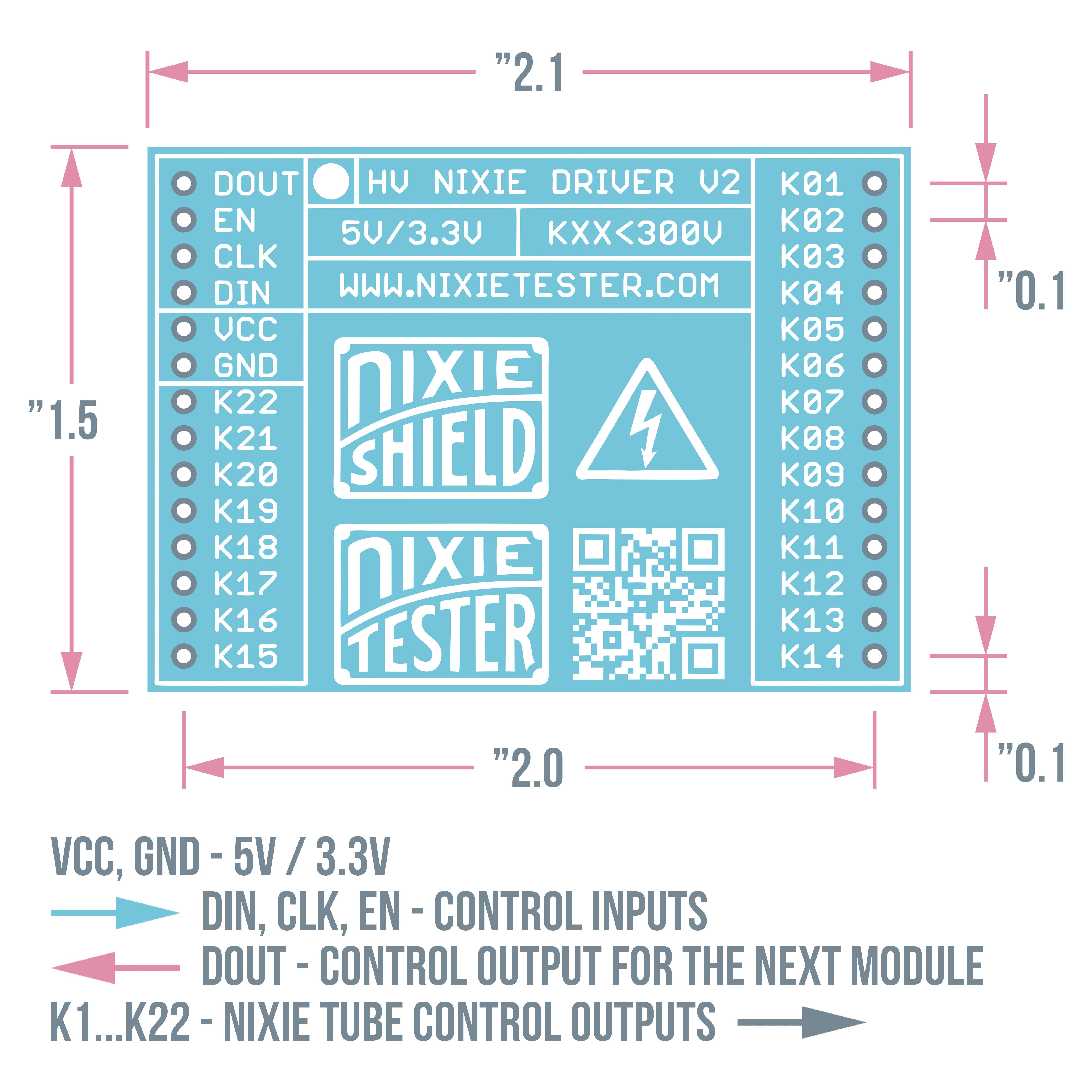
NIXIE TUBE DRIVER V2 - PARAMETERS
- 22 outputs for connecting the nixie tube cathodes (K1-K22)
- 300V off-state maximum output voltage
- Compatible with all 5V / 3.3V designs
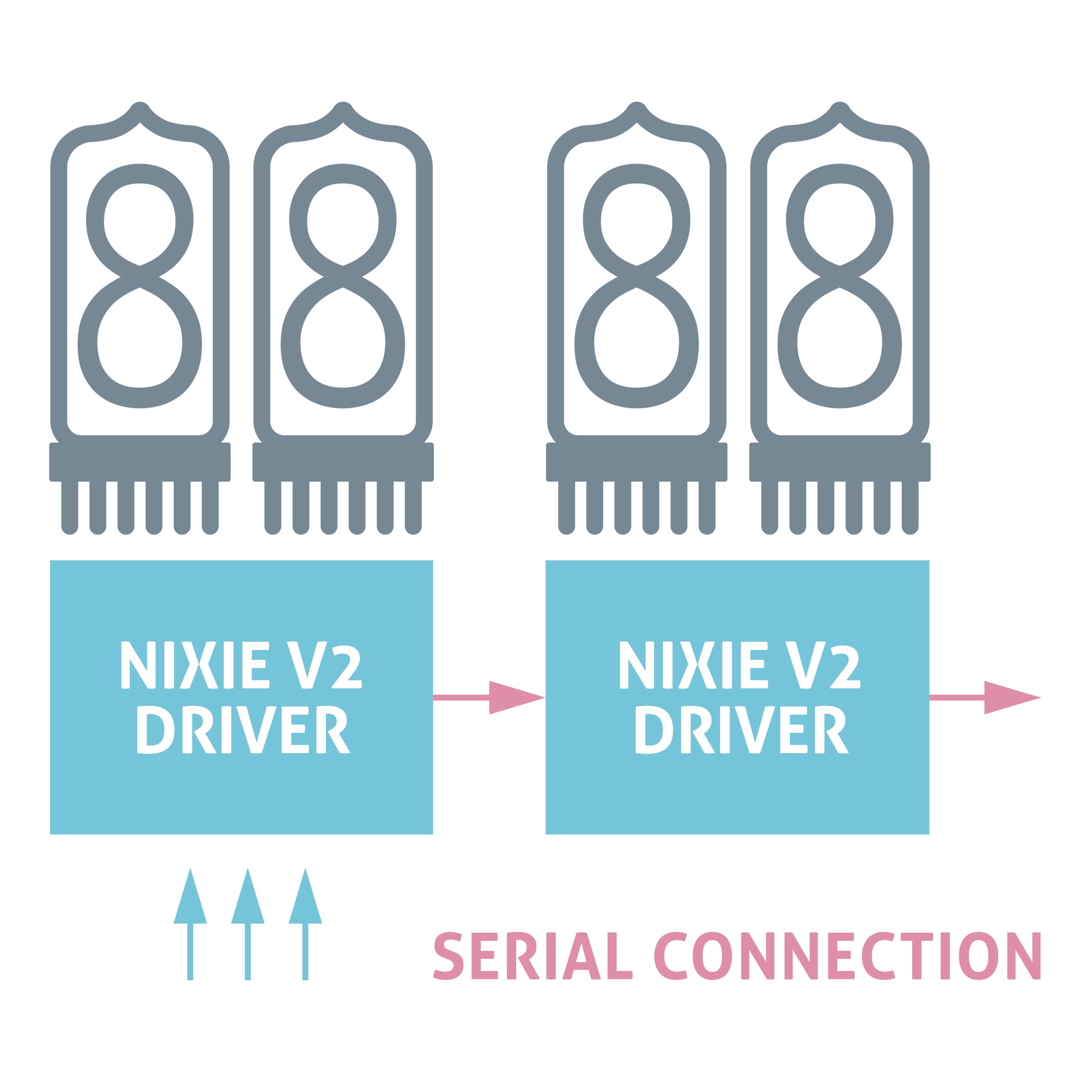
- Easy to use - only 3 control lines
- The drivers can be connected in series
More about Nixie Tube Driver V2 can be found on the project website.
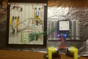
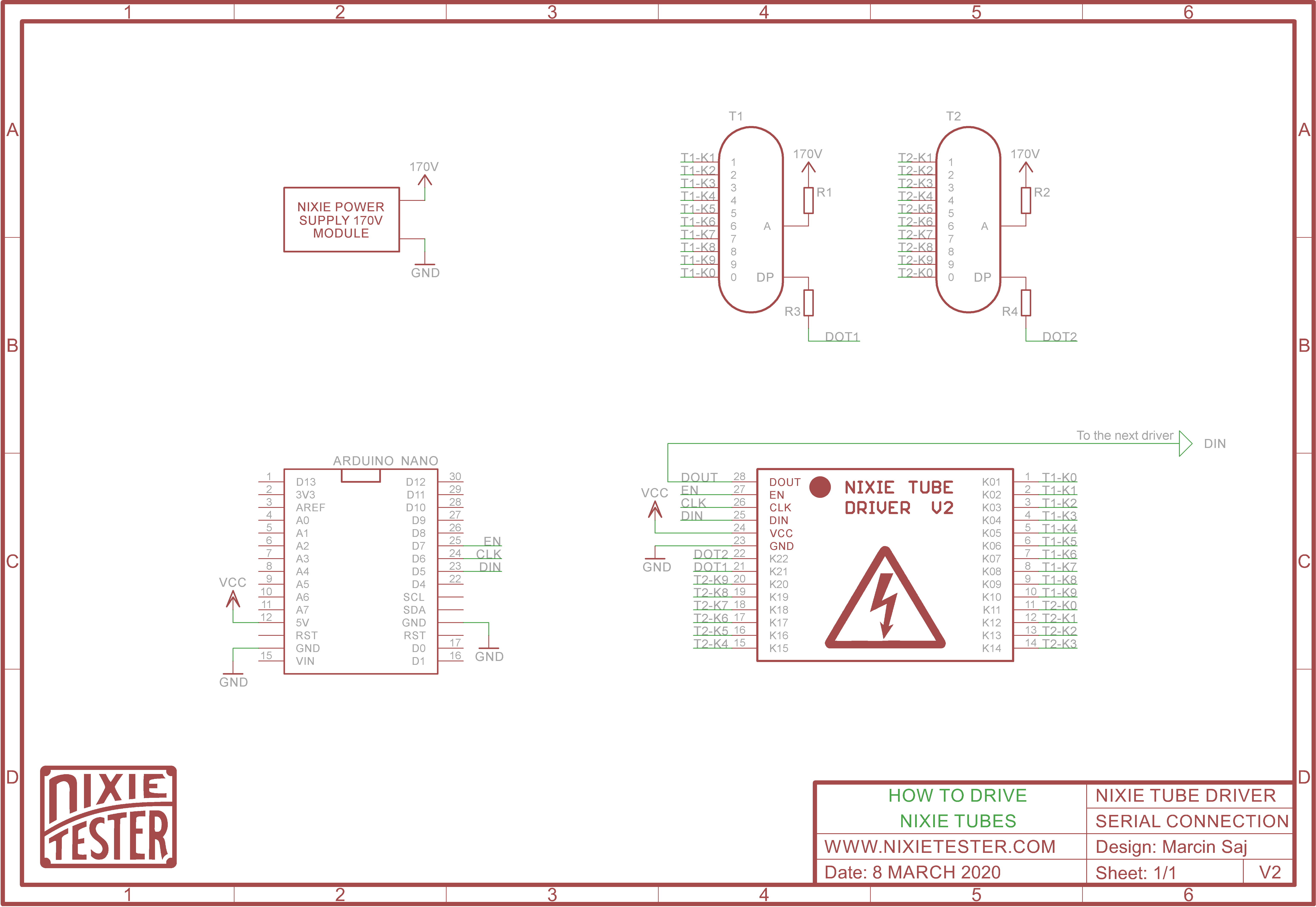
HOW TO CONNECT NIXIE TUBES TO THE DRIVER
There is only 3 control lines DIN, CLK, EN.22 outputs allow you to connect two nixie tubes with dots.
ARDUINO CODE
At the beginning we have to declare how we connected the individual nixie tubes cathodes:
// Bit array for 2 nixie tubes, dot1, dot2, 2 bits for gaps
boolean nixieDisplayArray[24];

// Cathodes assignment to the position in the 24 bit array
// Each cathode of nixie tubes is connected to the corresponding output of the shift registers
// Bit numbers
byte nixie1[]={
//   0   1   2   3   4   5   6   7   8   9
     0,  1,  2,  3,  4,  5,  6,  7,  8,  9 };
byte nixie2[]={
//   0   1   2   3   4   5   6   7   8   9
    10, 11, 12, 13, 14, 15, 16, 17, 18, 19 };

byte dot1 = 20;   // K21 nixie driver output
byte dot2 = 21;   // K22
nixieDisplayArray[24]; Why 24 bits if the driver has 22 outputs? If you take a closer look at the internal schematic of the nixie driver then you will notice that one of the shift registers has two outputs not connected. If we want to use several drivers connected in series, we must fill this gap for the correct transfer of data to subsequent drivers (registers).
Shift registers control program. You can also use any library to control shift registers, but for better understanding the program contains all the required steps to control registers without using the library.
void ShiftOutData()
{
  // Ground EN pin and hold low for as long as you are transmitting
  digitalWrite(EN_PIN, 0);
  // Clear everything out just in case to
  // prepare shift register for bit shifting
  digitalWrite(DIN_PIN, 0);
  digitalWrite(CLK_PIN, 0);

  // Send data to the nixie drivers
  for (int i = 23; i >= 0; i--)
  {
    // Set high only the bit that corresponds to the current nixie digit
    digitalWrite(DIN_PIN, nixieDisplayArray[i]);

    // Register shifts bits on upstroke of CLK pin
    digitalWrite(CLK_PIN, 1);
    // Set low the data pin after shift to prevent bleed through
    digitalWrite(CLK_PIN, 0);
  }

  // Return the EN pin high to signal chip that it
  // no longer needs to listen for data
  digitalWrite(EN_PIN, 1);

  // Stop shifting
  digitalWrite(CLK_PIN, 0);
}
Core of the control code:
void NixieDisplay(byte digit1, byte digit2)
{
  // Convert the desired numbers to the bit numbers for the nixieDisplayArray[]
  digit1 = nixie1[digit1];
  digit2 = nixie2[digit2];

  // Clear bit array except dot1 and dot2 bits
  for (int i = 23; i >= 0; i--)
  {
    if(i != dot1 || i != dot2) nixieDisplayArray[i] = 0;
  }

  // Set the bits corresponding to the nixie tubes cathodes
  nixieDisplayArray[digit1] = 1;
  nixieDisplayArray[digit2] = 1;

  ShiftOutData();
}
nixieDisplayArray[] - this is a bit array storing the current state of all nixie controller outputs. Storing the current state of the outputs is needed if you want to control tubes and dot points independently.
void SetDot(byte dotNumber, boolean dotState)
{
  if(dotNumber == 1)
  {
    if(dotState == HIGH) nixieDisplayArray[dot1] = 1;
    else nixieDisplayArray[dot1] = 0;
  }

  if(dotNumber == 2)
  {
    if(dotState == HIGH) nixieDisplayArray[dot2] = 1;
    else nixieDisplayArray[dot2] = 0;
  }

  ShiftOutData();
}
HOW TO DISPLAY "2.0"
Now the last step is the easiest part:
void loop ()
{
  // NixieDisplay(digit1, digit2);
  NixieDisplay(2, 0);

  // SetDot (dotNumber = 1/2, dotState = 0/1)
  SetDot(1, HIGH);
  delay(1000...
Read more »
 Johnny