 Mateo Estigarribia
For those who wonder why use a PIC16F887 and not some development interface such as arduino or perhaps raspberry, I can say that it is because in the school they made it a goal to use this microcontroller in order to increase our knowledge and perhaps as an entry to what would be typical of teaching such as arduino, raspberry or plc.
It costs me a lot to make a systematic explanation of how the project works, the truth is that we went in phases and perhaps therein lies the secret. The idea was to get the mechanical track system working first, then the radio communication system, and finally the robotic arm. The video camera is nothing more than a WiFi camera, we could not establish a connection to the xbee due to lack of time, we were against the clock and we no longer had time to investigate further, yes, I suppose it would have been some serial communication with TX / RX ports; In the same way, I have to say something very important, and that is that we deal with it in an extremely simple way to understand in every way, from programming, the use of components and mechanical structure.
So, let's start with the mechanical track part. It was an interesting challenge since we used the motors of the windshield wipers of the cars; These motors have a gear reduction mechanism, which at the cost of losing speed, gain a lot of force, are designed to be able to work in any condition, be it snow, sand, water. That is why they are quite efficient for this use. As a curious fact I can say that they could even carry the weight of my own body (72 kg or 158 pounds), I would think that they have the capacity to support double the weight of each of the motors working together, and I say motors because we use 2, not We wanted to complicate ourselves with no rare mechanism on the part of the mechanical tracks, just two motors that would work together, that would be able to go forward, backward, left or right.
It was simple to use motorcycle chains so that together with two sprockets per caterpillar, of which, one of them would be directly connected to the motor which would produce the corresponding movement. No other compliation with that part, the problem would come with electronics, how to control the direction of rotation of such robust motors that consume as much current as these? The answer was to use relays, which can handle considerable currents, and without a doubt, they were going to be able to spare with such heavy work.
So, in order to obtain the greatest robustness and simplicity possible, we made 2 boards, one for control and the other for power, the idea was to use an H bridge called L293D in the first stage, which, according to input signals, is capable of control 4 outputs, 2 for each motor respectively, where, depending on the aforementioned inputs, you could reverse the direction of current at the outputs. After that, optocouplers would perform the job of electromagnetically isolating and protecting said component (L293D) and also the robot's brain where the PIC16F887 would be and the outputs that control the entire system, which are 6. 3 for each motor where, looking at the datasheet of the L293D we can understand that for example, if we wanted to turn the motor to the left, we should enable the left input, disable the right turn input and an input that would always be enabled in our case, which is the PWM, We will not control the speed of the motor this time since it is very low by itself so it would not be necessary, we will only use the maximum speed of the motor.
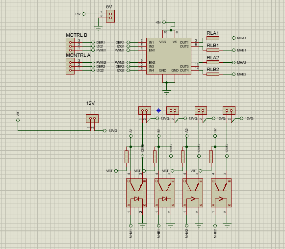
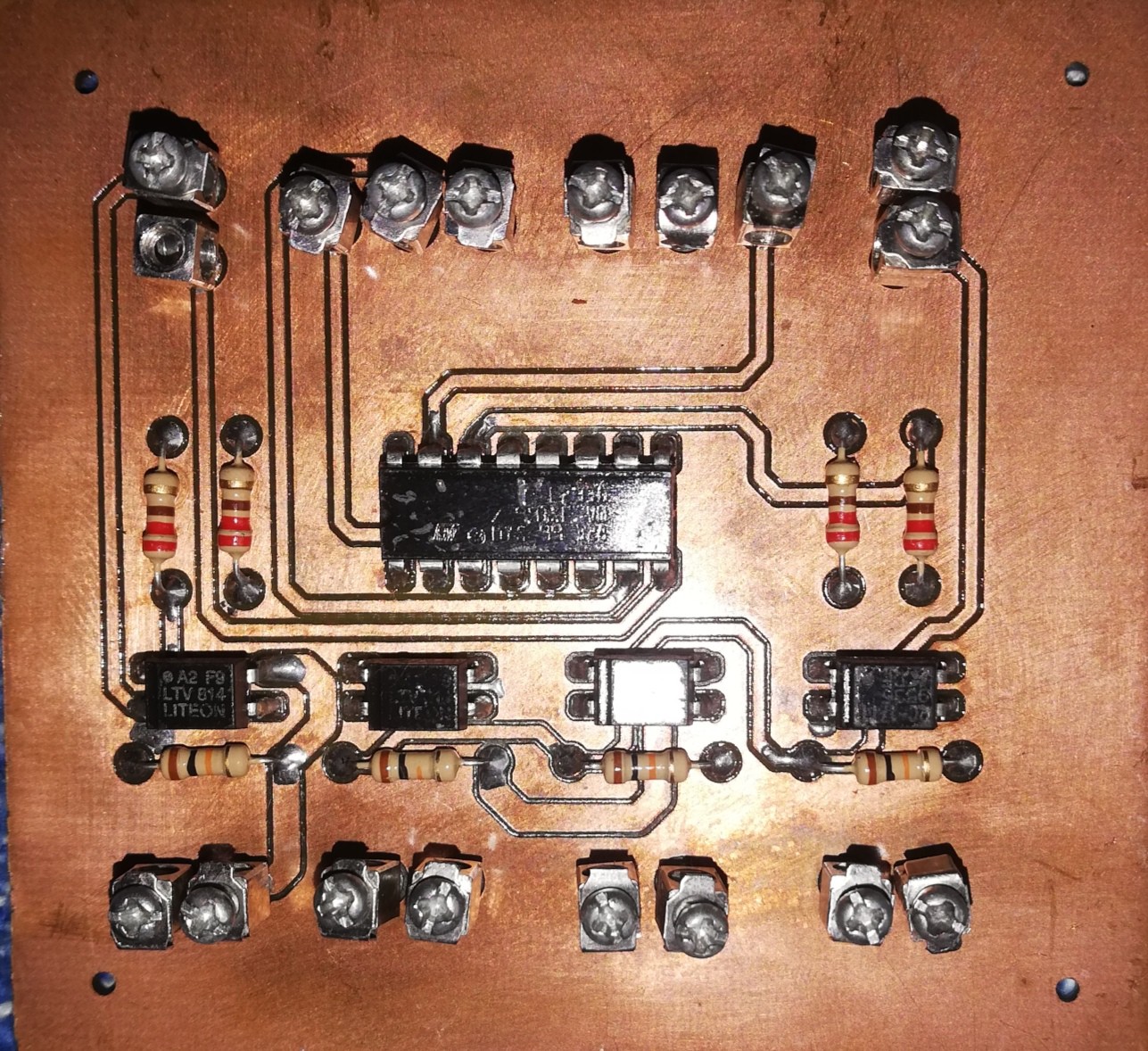
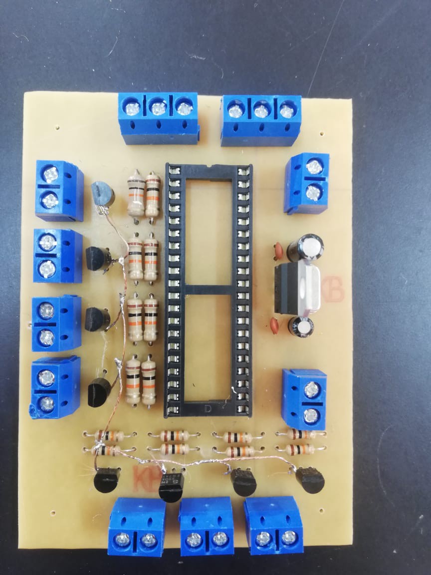
MCTRL A and B are the two inputs that the component has, and the outputs are already 4 that we can see after the optocouplers. The end result of the control board is this:
The programming is quite simple, pure if and else conditions, where depending on the input we have in the receiving PIC or brain that would be inside the robot, it would order the L293D to work. So as I explained previously, for example, if we wanted to move a motor in some sense, we should have a 1 in LEFT, 0 in RIGHT, and a 1 always activated in PWM (A motor turns to the left), and here is an example of how would the programming for it:
if(PORTA.RA0 == 1 && PORTA.RA1 == 0 && PORTA.RA2 == 0 && PORTA.RA3 == 0) //ahead
{
PORTC = 0x2E;
}
else if(PORTA.RA0 == 0 && PORTA.RA1 == 1 && PORTA.RA2 == 0 && PORTA.RA3 == 0) //behind
{
PORTC = 0x1D;
}
This programming is from the mechanical tracks, and we will find it in the folder proyecto_orugas.
To xbee we use it with its 4 I / O ports as point to point, so, when having the orders for the robotic arm, and the movement, they have to use another PIC in the remote control, so with the 4 ports, power have about 16 possibilities of which we would only use a few. In the receiver or brain, which would be the PIC housed in the robot itself, we would also have a similar system which, with 4 inputs and a deduction of the binary code in the program, would be doing the tasks. It is important to explain this since the if and else conditions shown above are based on this, using hexadecimal code to avoid putting so many zeros and ones; but that's something I'll explain later when I get to the wireless communication part.
Continuing then with the systematic part, after the control part would come the power part. Basically the control part activates the transistors and relays that the power section has; some TIP3055 more than comply with the work since they are robust and can withstand a lot of current, depending on what we have in the 4 outputs of the control board, then, it would be enabling the transistors and later the relays that would give the corresponding direction of rotation to the engines. At the output of the same we will find 12v and high or considerable current being able to reach 10 or more amps depending on the effort suffered by the motor.
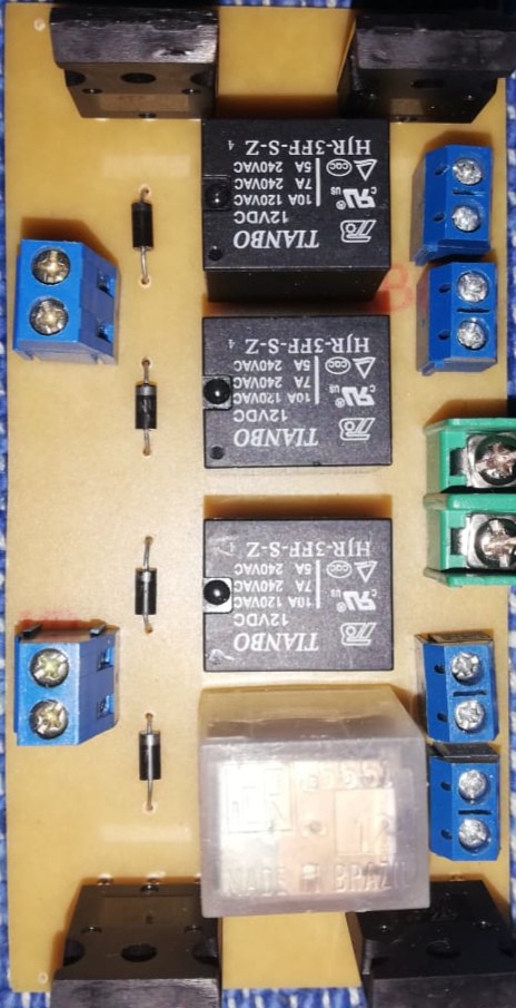
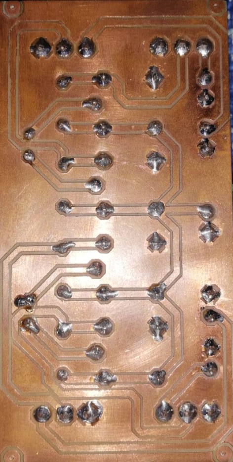
The 4 small terminals are the inputs where the optocoupler outputs are connected, the 2 on the other side are the outputs where the motors are connected and, finally, the green terminal board is where the 12v battery is connected.
The truth is that I could never finish the operation of the robotic arm, and it is something that maybe I will do in the future, or maybe not, suddenly there is a person here who really likes the project and is interested in improving and carrying out that part.
Well then, while perhaps I am leaving a million details aside, it is difficult to explain all this very well, but in the same way it may serve to have an idea of how I made the project. Anyway, without more words, there would end the part of controlling the mechanical track. Now we can talk about the part of wirelessly controlling the system.
As I said, the control would be communicated wirelessly through an XBEE, of which we will use 4 I / O ports that through binary code programmed in another microcontroller housed in the remote control itself, would be sending the data to the PIC of the receiver or brain to to be able to command orders. For example, if we have a positive input of the pull up of the go forward control button on pin RC0 of the PIC, then, the same in 4 outputs that in this case we choose the pins of port B would be sending there for example, 0000 , then, that binary code where each bit corresponds to an entry in the PIC of the brain, would be being programmed so that it can understand that it must go ahead, sending the commands to the L293D or better said, to the control board.
We can see here an example of programming on the remote control:
if(portc == 0x01) {
portb = 0x01;
}
else if(portc == 0x02) {
portb = 0x08;
}
So, to explain again, we have like 8 buttons where 4 are for the address and 4 for the robotic arm, and basically what we do is transform those 8 possibilities into a 4-digit binary code that would go to xbee for point-to-point communication. point, all this programmed in the PIC of the remote control.
Here a photo of how it ended:
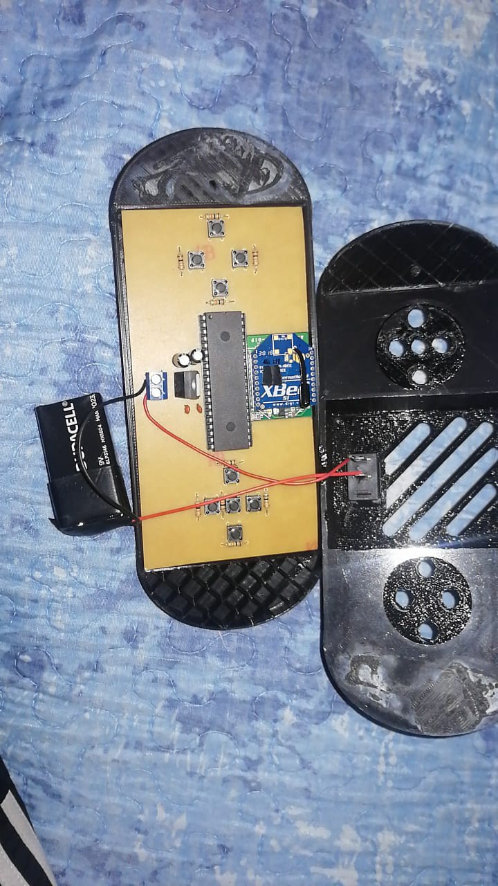
We can see that in the control we have an LM7085 voltage regulator that, with its respective configuration, stabilizes and regulates the voltage at 5v from the 9v battery, also observable. The same system is used on the robot's brain board.
Well, I think by explaining the remote control indirectly I already explained how the robot's brain works; here we can see a photo of it:
Well, there it is, and again, a lm7805 as a voltage regulator as I had said to have stable 5v, on the right we can see 2 terminals of which the one above is the input or 12v source, and the one below corresponds to a 5v output that would be used to connect to the control board. All the terminals below (3) are those corresponding to the receiving XBEE, one of them for its power supply, and 4 inputs which are the signal inputs.
All the terminals that are on the left side are used to connect to the servo motors of the robotic arm which only lacked programming, in the same way in fact we managed to close the clamp and perhaps some crazy movements experiencing, but it was far from working well, everything This is because we had almost no time to finish and the development became complicated, so we had to improvise.
Yes, the PIC is missing, unfortunately I can't find another photo of the brain board with the PIC on, but there you can see more or less how it was achieved. Interesting fact, also due to the lack of time, the pcb of the brain board was much uglier than the other 2, those of power and control. In the same way, it managed to be 100% functional.
Well, hoping that you have found this project interesting, I tell you that I am available to answer any questions you have. I tried to simplify the explanation as much as I could so that it is not so boring, and yes, I also left some details so that this is not so extensive. I hope you like it, I have a few more projects to share, and I will be uploading them depending on my availability of time, a big hug to the whole community.
PS: I do not speak English so well, I am Spanish speaking and I had to use the translator a bit, sorry for any misspellings.