 Jacques Gagnon
I always wait to have the software side significantly done before thinking about custom PCBs. I use DevKit as long as possible to allow for things to change easily. Also having something that looks like a final product in your hand before any software exists often just kill the project. Mentally it just looks like so much still need to be done and it's discouraging and overwhelming. Progressing slowly with DevKit on software is much better approach IMHO.
But for BlueRetro I think time has come to do the PCB design. Before doing so many steps had to be taken to simply come up with the current schematic, I finished this weekend. This log entry will document those steps.
MCU selection
Before any software or hardware work started on the project, I selected the ESP32 for a few reasons:
- MCU integrated with a dual Bluetooth radio (BR/EDR & BLE)
- Good community online around the chip
- SDK developed in the open on GitHub
- Shell/Makefile base development environnement
- Dual-core MCU
- FCC/CE pre-certified modules
Also while working on the software I discovered some others pro and (mostly ;) ) con for the chip:
Pro
- RMT peripheral, this allows to very easily generate 1 wire waveform via hardware. Without this, GameCube 4 players would be impossible since all four signals are simultaneous.
Con
- DPORT access bug, Cores halt each other when access required (Fixed in V3 silicon)
- GPIO interrupt latency around 1 to 2 us
- GPIO latency on set/clear around 0.5 to 1 us
- Many GPIOs are used for various strapping option
- Many GPIOs used for internal components
Now two years later, I think choosing the ESP32 was the right decision.
Using the chip for fast GPIO is challenging but I think this can be worked around with some creativity.
Available GPIOs
The first step in designing BlueRetro hardware was to list which GPIO are available. At first glance one might expect around 40 GPIOs. But many pins are used for boot strapping or for internal components of the module as listed below.
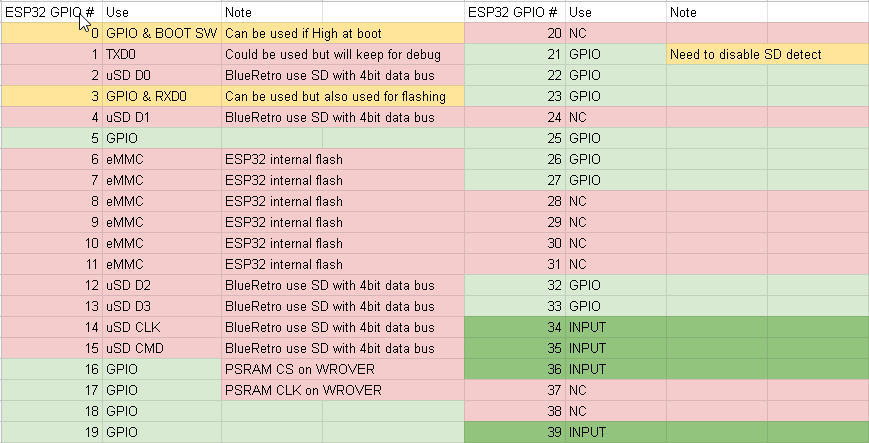
In the end, up to 19 IOs could be used with various limitation.
The project will support memory card emulation for N64 & Dreamcast at one point and so I wanted the SD card interface to use 4 data bits for maximum speed.
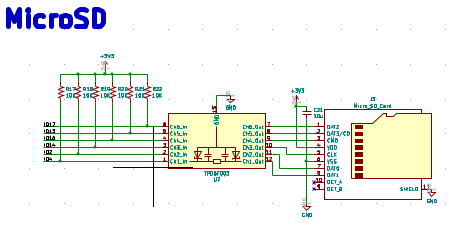
This point also triggered the decision regarding which of two ESP32 module types I will use. WROVER modules with their PSRAM got two less GPIOs. Since I'm not planning to use PSRAM, BlueRetro will use the WROOM module.
Power consumption
I still need to do some real world measurement specific to BlueRetro firmware but base on ESP32 datasheet I would expect the worst case with dual core, 240 MHz & Bluetooth to be around 300 mA.
I did some measurement back in the day for my Cube64 adapter for the N64 console. I think it's a good baseline as the N64 only provided 3.3v output on the controller port, forcing Nintendo to use 2 AAA batteries for the Rumble Pak accessory. PSX, PS2, Dreamcast & GameCube didn't require any battery for their rumble functionality and so I would assume they offered more power from their controller ports than the N64.
| Scenario | A on 3.3V rail | A on 12V rail |
| N64 + ExpPak + 2D | 1.300 | 0.075 |
| N64 + ExpPak + 3D | 1.700 | 0.075 |
| N64 + ExpPak + WideBoyCGB | 1.300 | 0.168 |
| N64 + ExpPak + WideBoyAGB | 1.300 | 0.260 |
| N64 + ExpPak + 64DD idle + 3D | 1.700 | 0.128 |
| N64 + ExpPak + 64DD disk access + 3D | 1.700 | 0.700 |
N64 power supply offer a max of 2.7A on the 3.3V rail. So we got around ~1A available for all 4 ports if we consider the worst case of 1.7A.
Let's add a safety margin of 20% that gives us 0.8A available for BlueRetro since only one adapter is required for multiplayer.
I will need to perform those same tests for all systems I plan to support.
System detection
Unlike other adapters that target only one system or need compile flag or configuration beforehand, BlueRetro shall detect most systems automatically.
At first I had in mind to fingerprint the received waveform with the RMT hardware but that turn out to be quite complex to do.
A better and easier solution is to simply stage the pinout so that only one system will have one of its output pins on one of the ESP32 GPIO. All other system would use that same pin as an input.
On boot BlueRetro configure all the detection GPIOs as input with interrupt. Once one of the system outputs changes this raises an interrupt and BlueRetro identify the system base on which GPIO raised the interrupt.
It's important for unused detection pin to be grounded to avoid interrupt from floating pins.
A drawback of this is that the adapter won't answer the first few requests coming from the system but base of tests so far this is never an issue. If this turn out to create detection problems with some games, it's also possible to force the system via the configuration. Also simply resetting the console once would resolve those issues since the adapter stay powered on and set to the previously detected system.
Some system does not output any signal and can't be detected. As a compromise some IOs are reserved to offer a minimal 1 player Atari style output while the adapter is in detection mode. Multiplayer for those systems will, however, require the system to be explicitly configured.
It's also possible to use some of the detection GPIOs for output from system as long their state will not toggle before that system assigned detection pin. As an example for PSX/PS2 the ATT line toggle low significantly upfront of the CMD & CLK line on port 1 to ensure proper system detection.
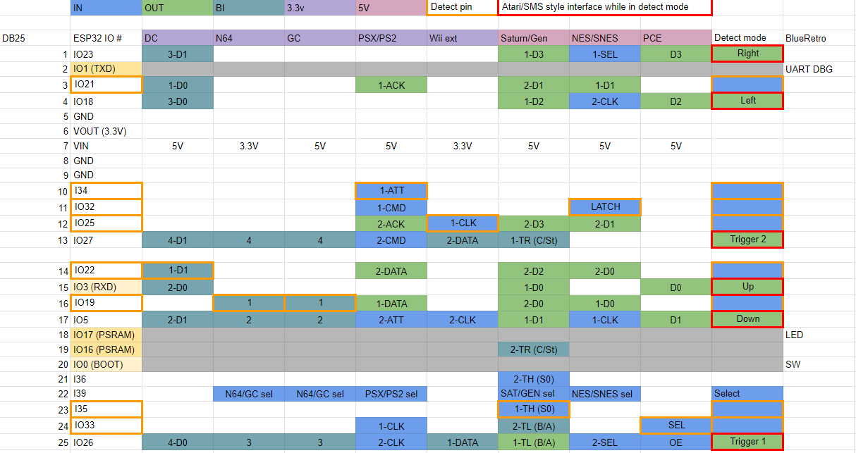
In the end, 8 GPIOs are used for system detection via interrupt and another input only pin is used to toggle between 2 systems on the same detection IO. This make possible for BlueRetro to detect up to 16 systems.
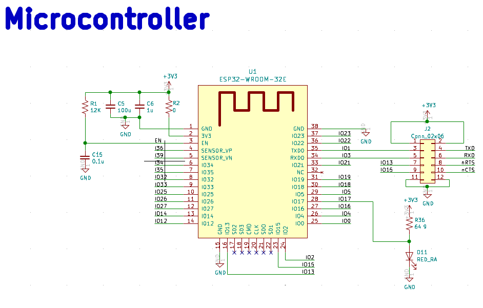
Interface connector
While I might sell some adapter cable early on, the objective here is to have easy to built DIY cable adapter kits to go with the BlueRetro core that I will offer.
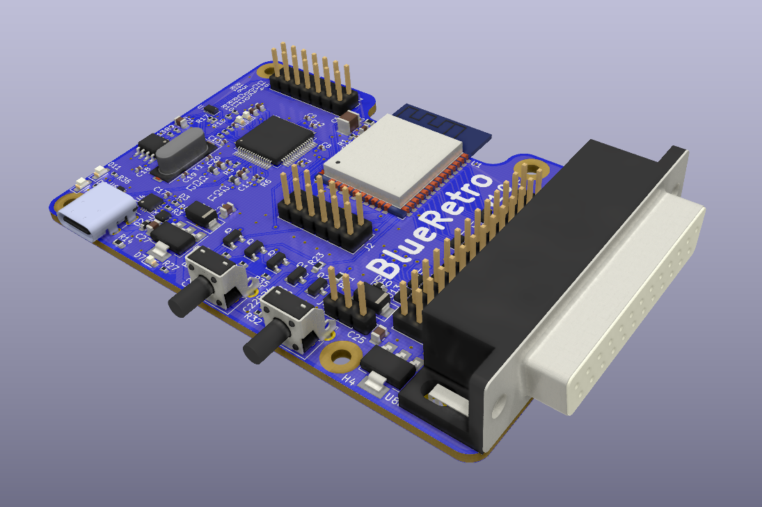
My first idea was to use 4x RJ45 connectors since it was very simple to crimp but many system uses more than 8 pins (Atari, Genesis, Saturn, NeoGeo, etc.). In the end, I decided to go with a unique DB25 connector since it offers enough pin to expose all the available ESP32 GPIOs + power pins. Also the pins are big enough to be DIY friendly. Another advantage is that the connector shell is big enough to host a small PCB.
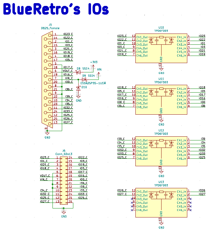
All ports for each game system (between 2 & 4) goes to that centralized connection. The adapter core expose a 3.3v interface and so the cable end need to include level shifter for 5V systems. Any special PHY like RS232, RS485 or USB will need to include the PHY on the cable end.
BlueRetro ESP32 DevKit
Since BlueRetro firmware is still in a very early stage, it doesn't make sense to design a board as if it was a final solution at this stage.
The first board design will be under the form of an ESP32 DevKit that includes the BlueRetro interface.
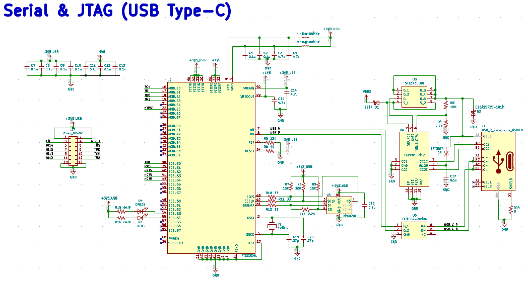
Using Espressif official DevKit is not ideal since the DevKitC is missing too many components and the WROVER-Kit got too much stuff interfering with the BlueRetro interface. Also both official DevKit are designed to supply power to the MCU via USB. While it is useful to have the USB serial bridge power from USB, it is better for me to have the ESP32 powered from the game system.
This allows me to get early logs when I power up the game system. I will use the FT2232HL USB serial bridge for the JTAG debug functionality.
Any early BlueRetro user will be able to order this board and participate either in the development or testing of the project. Having all the debug facility included in the board will make remote troubleshoot session at lot easier for me.
The BlueRetro ESP32 DevKit will be very similar to the WROVER-Kit with the following difference:
- BlueRetro DB25 GPIO interface
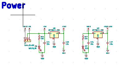
- Two 3.3V power domains, one for USB serial bridge the other for ESP32
- Low voltage drop LDO for system providing only 3.3V (simplify cable adapter to have only one VIN)
- USB Type-C connector
- No LCD
- No 32KHz clock
- No RGB LED
- No Camera header
I decided to go on the safe side with the design and included ESD protection for all external IO. Also I added protection for VBUS 20V supply and for CC pin short to VBUS. This raise BOM cost a bit but I rather avoid dealing with the possible issue in the field of not having those protections. Using FT2232HL also raise the cost but having a standard chip for serial and JTAG on consumer board will be very useful for debugging. This also makes the board very interesting as a standalone ESP32 DevKit for other projects unrelated to BlueRetro.
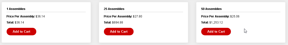
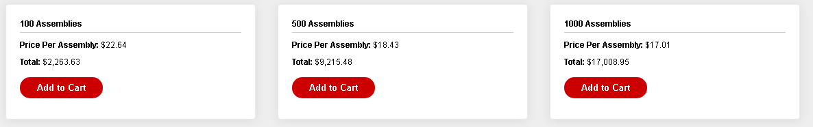
The BOM sum to 36 USD for a single unit and at around 25 USD per unit for 50 units. Add to that around ~5 USD per 4 layer PCB, ~10 USD for basic assembly and *2 for my time we get (25+5+10)*2 = ~80 USD for a 50 boards run.
This is a bit high but my BOM is not very optimized yet and PCB + Assembly could be cheaper. I could reduce my cut too :). I think I should aim for a price at around what the official WROVER-KIT cost is: 40 USD. Maybe 50 USD doable.
PCB Form Factor
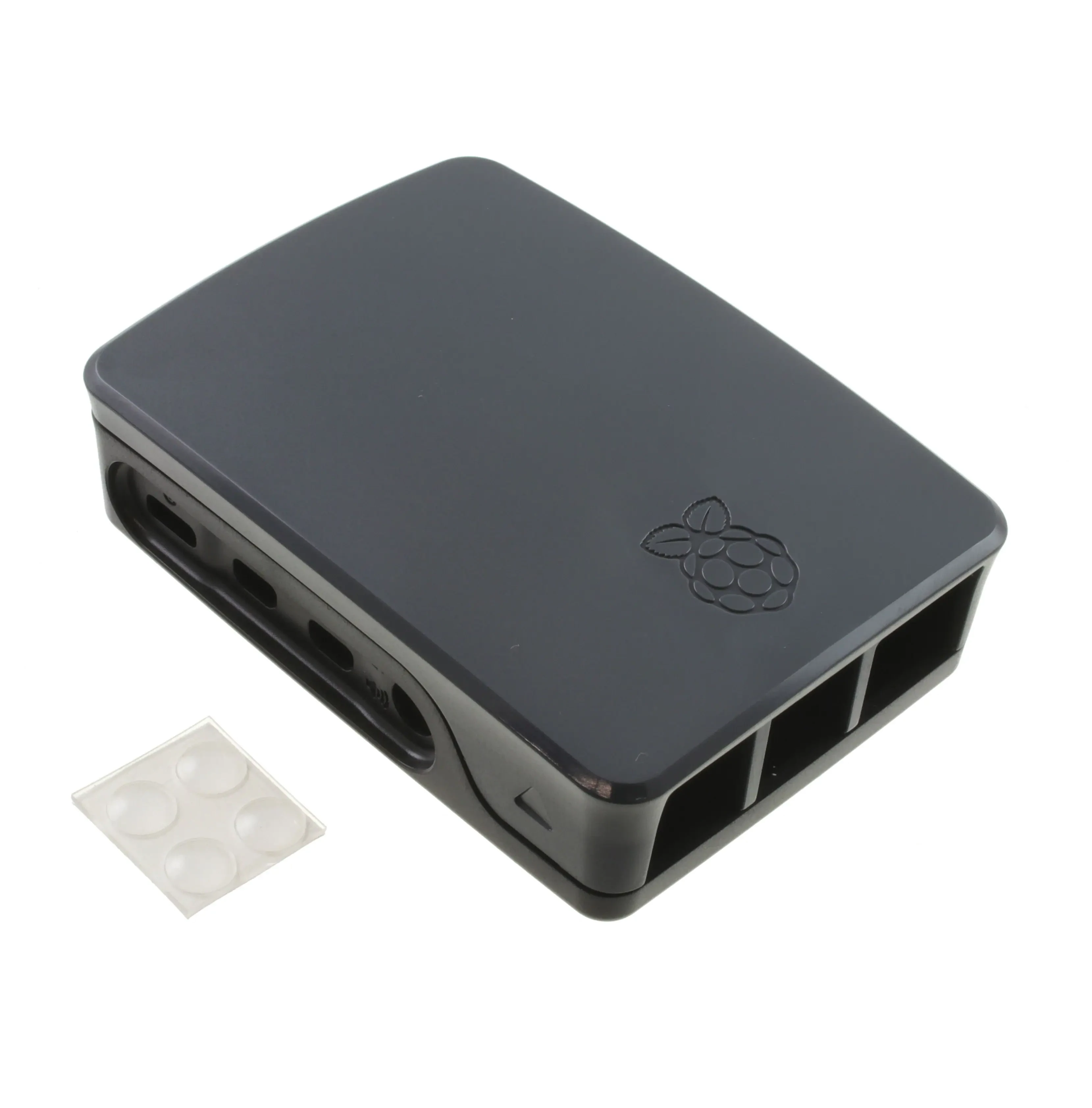
I decided to use the same form factor as the Raspberry Pi 4 to enable usage of existing mounting and case solution.
The DB25 connector will be located where the Ethernet & USB hub are.
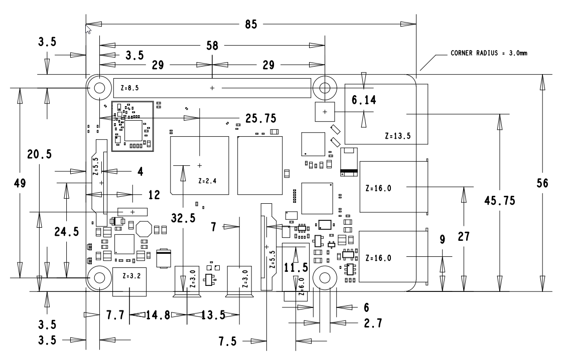
Modding an existing case should be very easy by cutting only 2 narrow plastic tab. Power LEDs, USB Type-C and microSD will use the existing RPI location.
The HDMIs and audio connector location will be used for the USB activity LEDs and the 2 buttons.
Plan B
The big unknown still remaining is if I will be able to support every system using only the ESP32 GPIOs. If not my plan B will be to use a Lattice 4000ZE series CPLD in the cable adapter of the eventual problematic system.
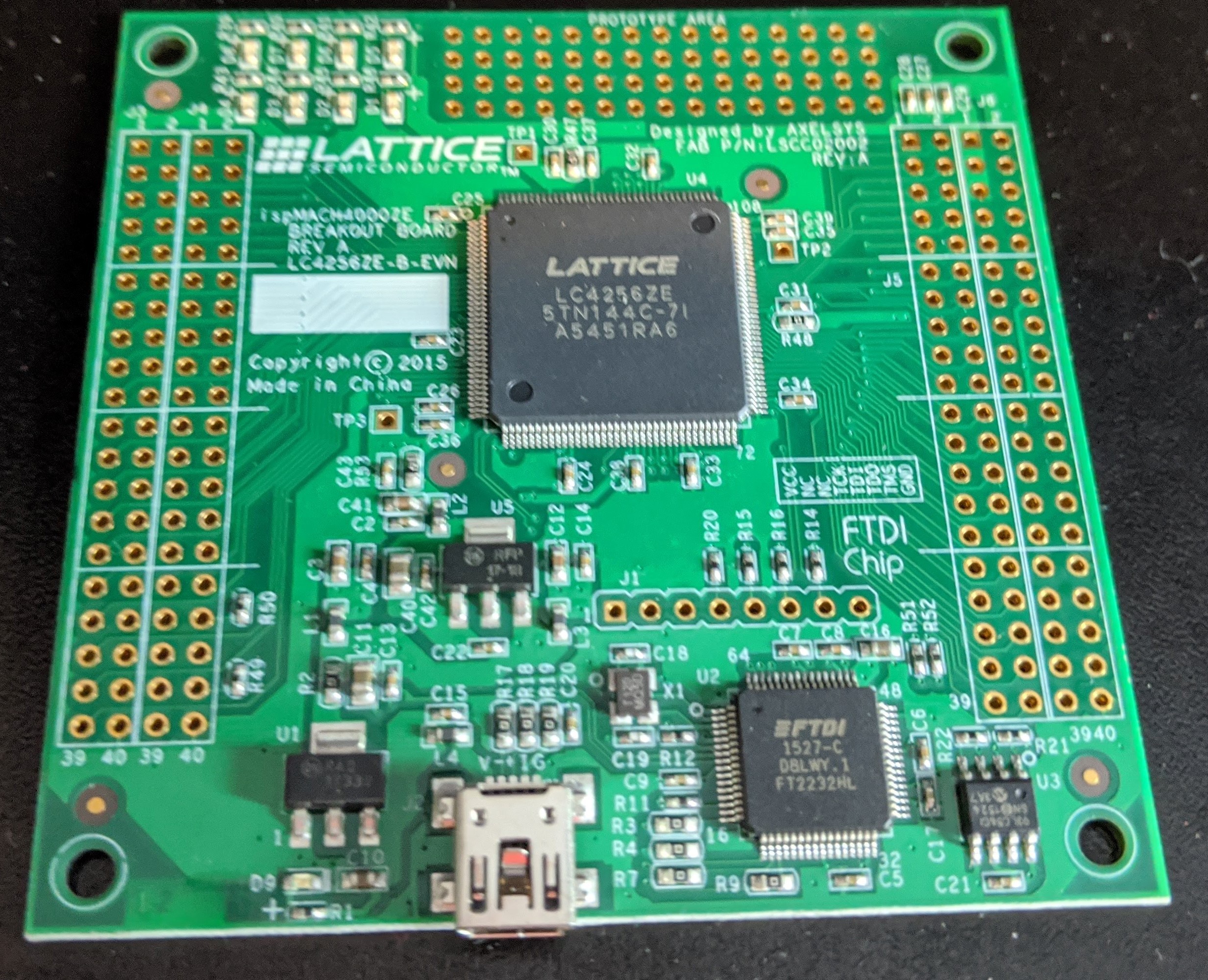
Instead of writing Bluetooth controller state in shared memory they will be written directly on the CPLD via SPI. The fast logic of the CPLD will then implement the wired interface of the system. I chose this family of CPLD because they are the only current chip with 5V tolerant IOs. I will use this chip anyway for systems with too many IOs like the Atari 5200, Jaguar or NeoGeo.
Discussions
Become a Hackaday.io Member
Create an account to leave a comment. Already have an account? Log In.