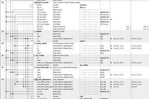
Close
0%
0%

SBC-85 Bus Monitor Supreme

Bus monitor card for SBC-85 ecosystem. Includes binary and hex display of bus and data byte, single step, slow step, and breakpoints.

Similar projects worth following
Starting from
$5.00
ccandrews has 94 orders / 1reviews
Ships from United States of America
After the SBC-85 CPU card and backplane, the next order of business was a bus monitor. Not just any bus monitor with blinking lights, but one with single stepping, automated slow stepping, and programmable breakpoints. A tremendous challenge to fit on my goal of 125mm x 150mm 2-layer. I wanted this card to be slightly larger than the SBC-85 so the HEX displays would show over a standard height card and the single step buttons and bus status LEDs show to the left of a standard card.

While the bus monitor itself is a super useful tool, for anyone that wants to get into the weeds with the details of the 8085, a bus monitor is a good place to start.

The SBC-85 Bus Monitor includes LEDs for the traditional binary display of the system's 16-bit address bus and 8-bit data bus.  Because I sometimes think faster in hexadecimal rather than binary (and sometimes vice-versa), I wanted to have not only binary display but a decoded hexadecimal display of the address and data byte.  The bus signals are also brought out to LEDs (towards the left side of the board) visible past a standard 100mm x 100mm card like the SBC-85 CPU.  All bus signals are buffered to minimize loading of the backplane.

To make the bus monitor more useful as a diagnostic tool, I also included a single step mode and 'step' button.  In addition, sometimes it is annoying to have to single step while watching code so there is an onboard pulse generator (555 timer) to generate a 'step' pulse train.  A finger potentiometer allows easy adjustment of the step rate from 60Hz down to about 0.5Hz.  Finally, an onboard port allows the user to programmatically control the step by disabling the step function during boring portions of the code and re-enabling during the portions of interest.

An added feature of the step is the ability for the user to select what type of machine state is used to trigger a stopping point for the step.  For example, the step can be configured to step from port output to port output, memory read to memory read, opcode fetch to opcode fetch, etc.  This is a tremendous tool, for example, to focus on the portions of the code that are writing to IO ports, or reading from memory, etc.  The choice of what type of machine state is used can be set by an onboard rotary switch and the choice is shown by illuminating a LED representing that specific machine cycle type.

The board actually consumes four I/O ports with the base port being a configuration port with items such as the step over-ride and a speaker toggle.  Additionally, a set of jumpers determines if the onboard rotary switch sets the machine type filter or if these are set via software control.  The upper three ports allow the user to set breakpoints for the low and high address bytes as well as the data byte. 

Breakpoint matching is a great diagnostic tool usually reserved for in-circuit emulators and CPU monitors like the Intel uScope 820.  On this bus monitor the user can write match values to the three registers and then individually enable or disable the breakpoints via software.  For example, it may be handy to break anytime a given data byte is placed onto the data bus, or anytime the most significant byte of the address matches a value (or, optionally is greater than a value). Or possibly limit the breakpoint to when a specific address is placed on the bus.  All possible with this bus monitor.

SBC-85 Bus Monitor Users Manual v0.9.pdf

SBC-85 Bus Monitor Supreme User's Manual (Description, Schematic, BOM, etc.)

Adobe Portable Document Format - 216.61 kB - 03/13/2020 at 22:58

Preview
Download

  • Version 1.1, so far, so good.

    Craig03/25/2020 at 23:49 0 comments

    Received a fresh shipment of boards from PCB house a couple of days ago and among them was version 1.1 of the bus monitor supreme.  I have pretty much assembled everything and am well into the testing phase.  All the issues that i wanted to correct from version 1.0 seem to have been corrected OK, except one capacitor that I had added to make the single step reset signal more robust.  Fortunately, I was able to depopulate and save all of the LEDs and nearly all the capacitors and other pricey items.  However, in the desoldering we lost the momentary single step push-button so I need to get another one on order.

    I really like having both the hexadecimal and binary display of the address and data.  I also really like the machine cycle type filter, it is impressive to see it jump from memory write to write, read to read, and so forth.  Heck, I think I like everything so far about this bus monitor.

    If everything continues to go well with the testing, I will release this version of the build files on the SBC-85.COM project site.

  • Bus Monitor Supreme From Prototype to v1.1

    Craig03/13/2020 at 23:35 0 comments

    I don't wirewrap anything anymore, so i go directly to a PCB.  The prototype PCB was received in January and has been built.  I messed up the placement of some of the LEDs and didn't like the way the single step reset would occasionally miss a button press or it would take two presses to get the step to advance.  The guy that sold me the decoders for the 7-segment displays sent the wrong part (shipped surface from overseas) so I was out another 5-6 weeks waiting for the correct component to arrive.  Rather than finish the build of this board, I decided to go ahead and make the revisions I wanted and get version 1.1 on order.  Since the decoders are coming surface and the PCBs by express, they both should be arriving before the end of March.

    On version 1.1. of the layout I fixed the LED placement and did a little modification to the reset logic to make the step reset more reliable.  There were also a few LEDs that kept confusing me, like the "pulse train" LED which was meant to show the user how quickly the step pulse train is but it is always blinked even if the board is not in the automatic 'slow step'. Since this caught me off-guard a few times (thinking it should be stepping when it was actually in manual step) so I changed that LED to reflect when the 'step' command is given either by a button press or by the pulse train.  There were a couple other changes to the LEDs along those lines, hopefully to more clearly describe the board condition at a glance.

    The biggest thing I changed in v1.1 is swapping out the bus type filter BCD rotary encoder for the complement output version.  In the original design I was fighting the natural input pull-ups of the logic devices with pull down resistors of my own connected to the encoder.  I knew better, but I decided to go that route because I already had the switch.  Mistake made, lesson learned.  While it worked OK, the signal levels were nothing to be proud of so in v1.1 I switched all the logic so the pull resistors were now going in the direction the signal wanted to go anyway.  So much for saving $5 by using a switch I happened to already have.

View all 2 project logs

Enjoy this project?

Share

Discussions

Similar Projects

Does this project spark your interest?

Become a member to follow this project and never miss any updates