 Craig
CraigThe first task was to write the code to output the bursts and spaces. 30 or so lines of assembly code later and that is done.
Back to the hardware......Here is the schematic
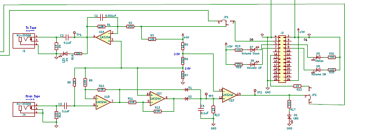
For the first test I simply looped the output directly back into the input and went through the various test points with the scope to see if the signals were as expected. For the most part, the hardware worked as designed, one tweak on the resistor value R6 which is the threshold value used by comparator. With a normal 0.6V drop across the two summing diodes D1 and D2, the summed signal (at TP3) was not quite high enough to trigger the comparator U1D to swing to the high rail. In the end, I put in a 0-ohm for R6 so that the DC output of U1B and U1C is the same as the reference voltage for the comparator U1D. That done, the signals started popping out the comparator and TP2 is getting nice rail-to-rail swings. To better integrate the spikes at the summing point, R12 went up to 10K. I think that I am going to call it on the hardware. Something may pop up later, but things are good to move on.
Here is what the output of an ASCII SPACE looks like with the output looped back to the input. The top line is the output to the tape, middle line reference spikes, bottom line the signal at JP2, i.e., the end result after the output character is read back and integrated over the bursts. (To save you the trouble, a space is 0010 0000 which is why we used to always use it to auto-set the baud rate). Timing spikes on one of the LEDs were added to help find the beginning of each character and data bytes are sent LSBit to MSBit. While logic probes can fudge the voltage levels, on the scope the input to the CPU is a hard 0V to 3.8V.

Immediately following the first marker the bit pattern is 0 0 0 0 0 1 0 0 0. The trailing zero is used as the starting point for the data input routine. After the 8-bits of data are received the input should be the tone burst of the 9th bit (trailing zero) and the code loops here until the end of the burst. Much like one would wait watching for a start bit on a serial input.
This afternoon's project is to write the data byte input code which is where I will pick up next time.
Discussions
Become a Hackaday.io Member
Create an account to leave a comment. Already have an account? Log In.