 Guy Dupont
In my previous log, I mentioned that I'd be laser cutting a chassis for my hardware. However, COVID-19 has temporarily eliminated my laser access, so I am going to trying to make do with the 3D Printer I have at home (an Ender 3 Pro). Rather than cut holes into a sheet of acrylic, I'm going to print flat slabs of ABS with holes baked in. And since I'm using OpenSCAD, I can programmatically add standoffs and such at no cost. This will save me some glue/screws later on, hopefully. Worst case, if the prints don't work for some reason, I can generate 2D projections of my files and quickly revert to the laser-based plan.
First Pass
Using the vector graphics that I produced for the face plate, I derived a master DXF file with 5mm circles at all of the locations that I would need LEDs to sit and shine behind it. I added accompanying 3mm circles for M3 screw holes. The screws would be used to keep the light "barrels" attached to the chassis, and also hold a thin back plate parallel to the chassis. This would keep all of the LEDs locked in place.
I broke the master DXF file into 5 segments, so that each could fit on my printer's bed. There are 2 segments for the clef side of the visualizer (top and bottom), and 3 for the keyboard side (left, center, and right). I created 2 SCAD files for each segment: one for the main chassis piece, and one for the back plate. Though I need one SCAD file per printable piece (10 total), I was able to consolidate much of the common code between them. Each file essentially only contains a pointer to the corresponding DXF file with the holes in it, and a list of (X, Y) coordinates for standoffs. This way, if I want to change any parameters of the total build (platform height, standoff circumference, etc), I would only have to change the code in one common file. I also added a master "assembly" SCAD file that dynamically loads all of the individual pieces into one view. This is the only file I kept open with the OpenSCAD GUI, as it would show how any individual change would impact the whole system. The way it's set up, any change to any DXF file automatically propagates all the way down the final assembly. Parameterized CAD FTW. You can see the structure, along with a bit more detail, here. As of the time of this post, the only files included are for the clef side of the visualizer.
Here are some renders (again, clef side only):


The yellow and blue pieces represent the top and bottom of the chassis, respectively. The green and red represent the accompanying back plates. The slits are to allow the leads of the LEDs to poke through. The lip of the bulbs get sandwiched between the front and back chassis pieces (between yellow and green for example. The orange piece is the "barrel".
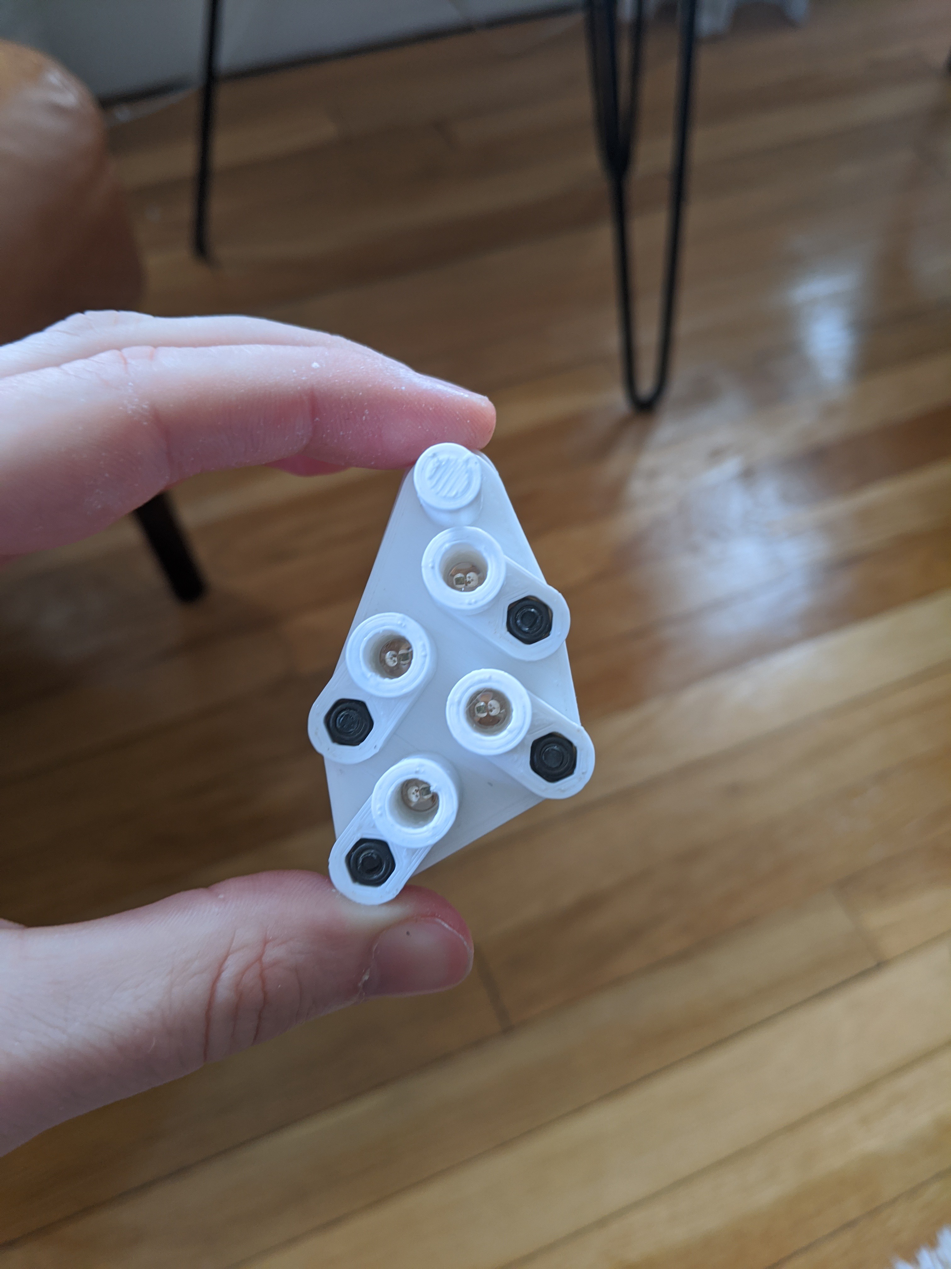
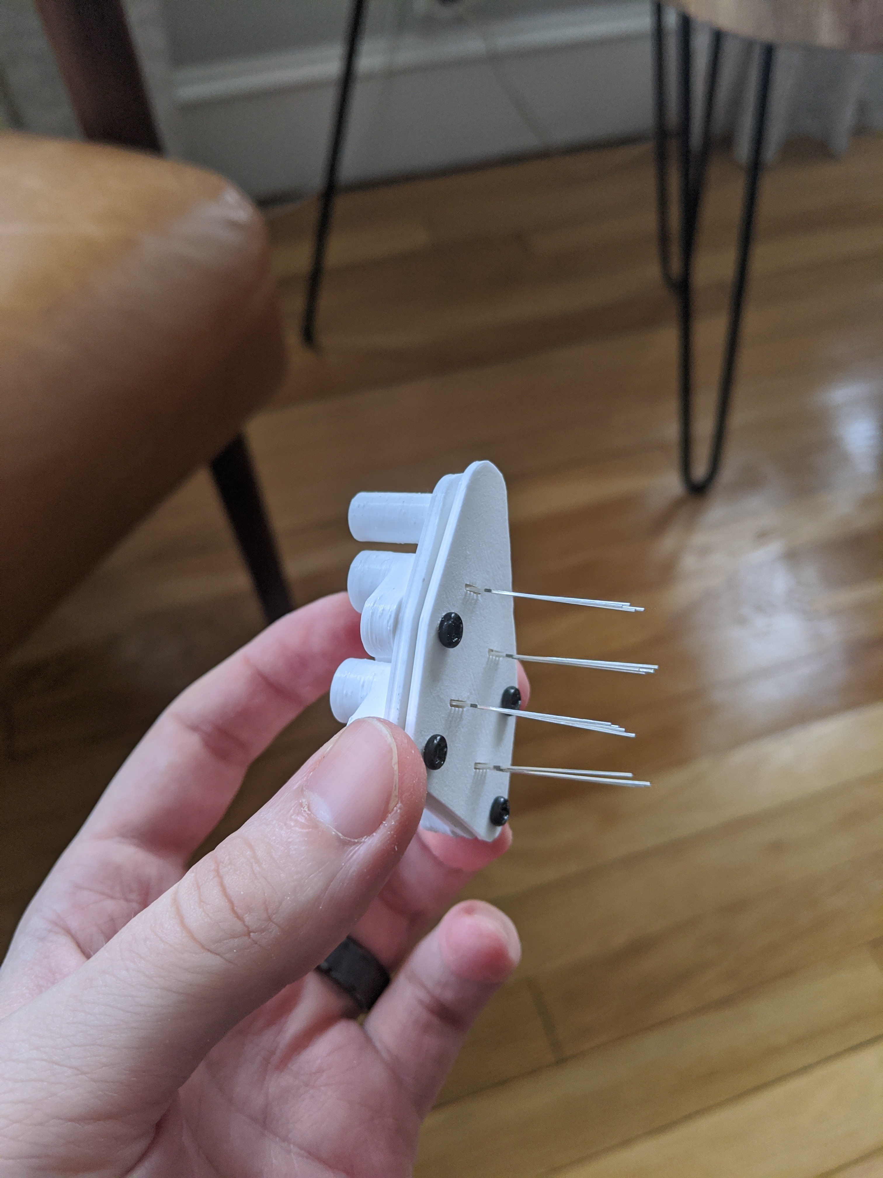
Here are some shots of a small test print with bulbs and screws in place:
Discussions
Become a Hackaday.io Member
Create an account to leave a comment. Already have an account? Log In.