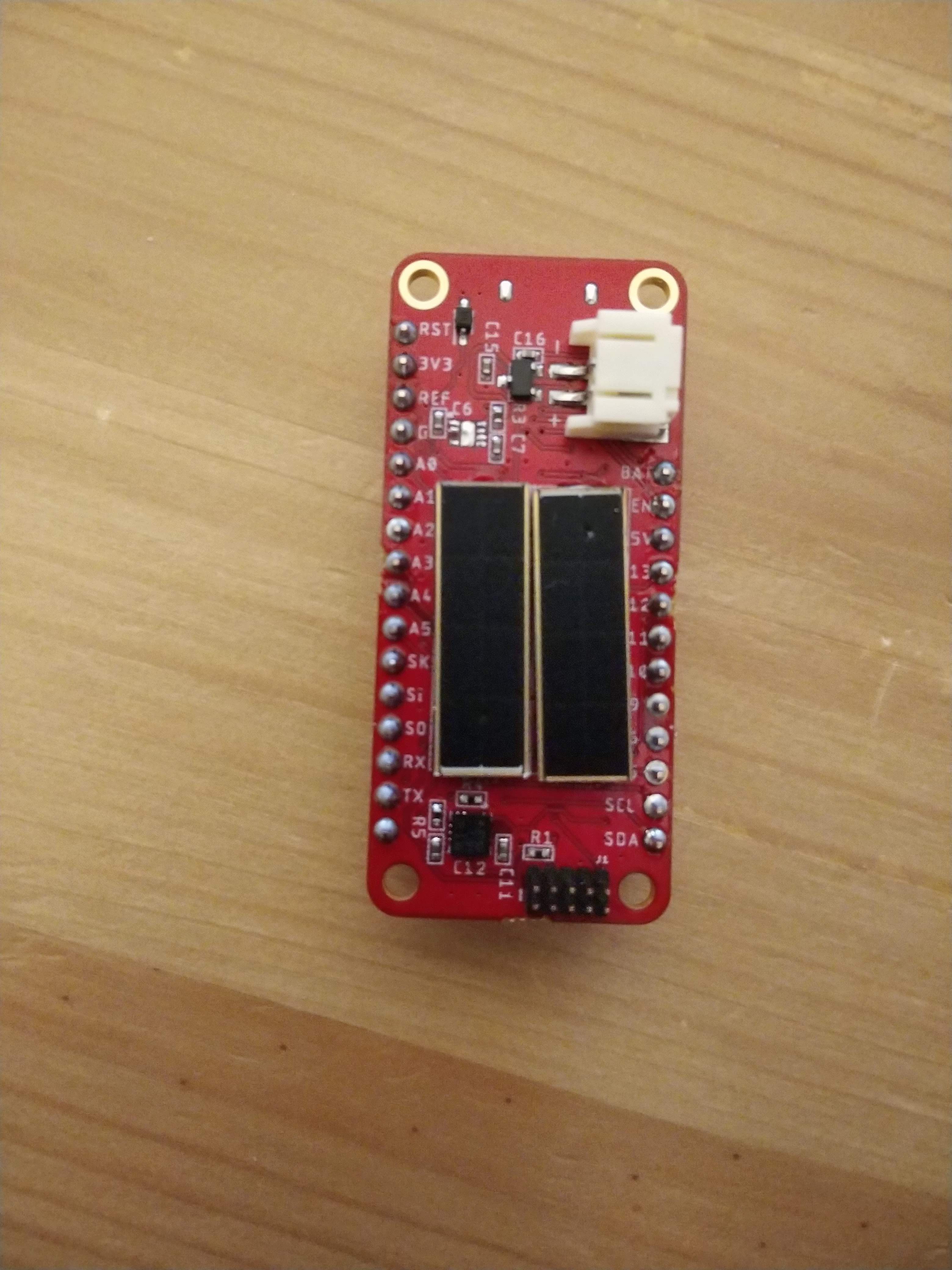
Version 1 of the hardware arrived, and I have been testing it. Almost immediately, I discovered I had made a connection mistake on the 3.3V regulator, and the system would not run normally from battery power. I desoldered that part, and by providing 3.3V directly to the 3.3V rail, I was able to program and test the rest of the board. The picture below shows the board with the 3.3V regulator missing.
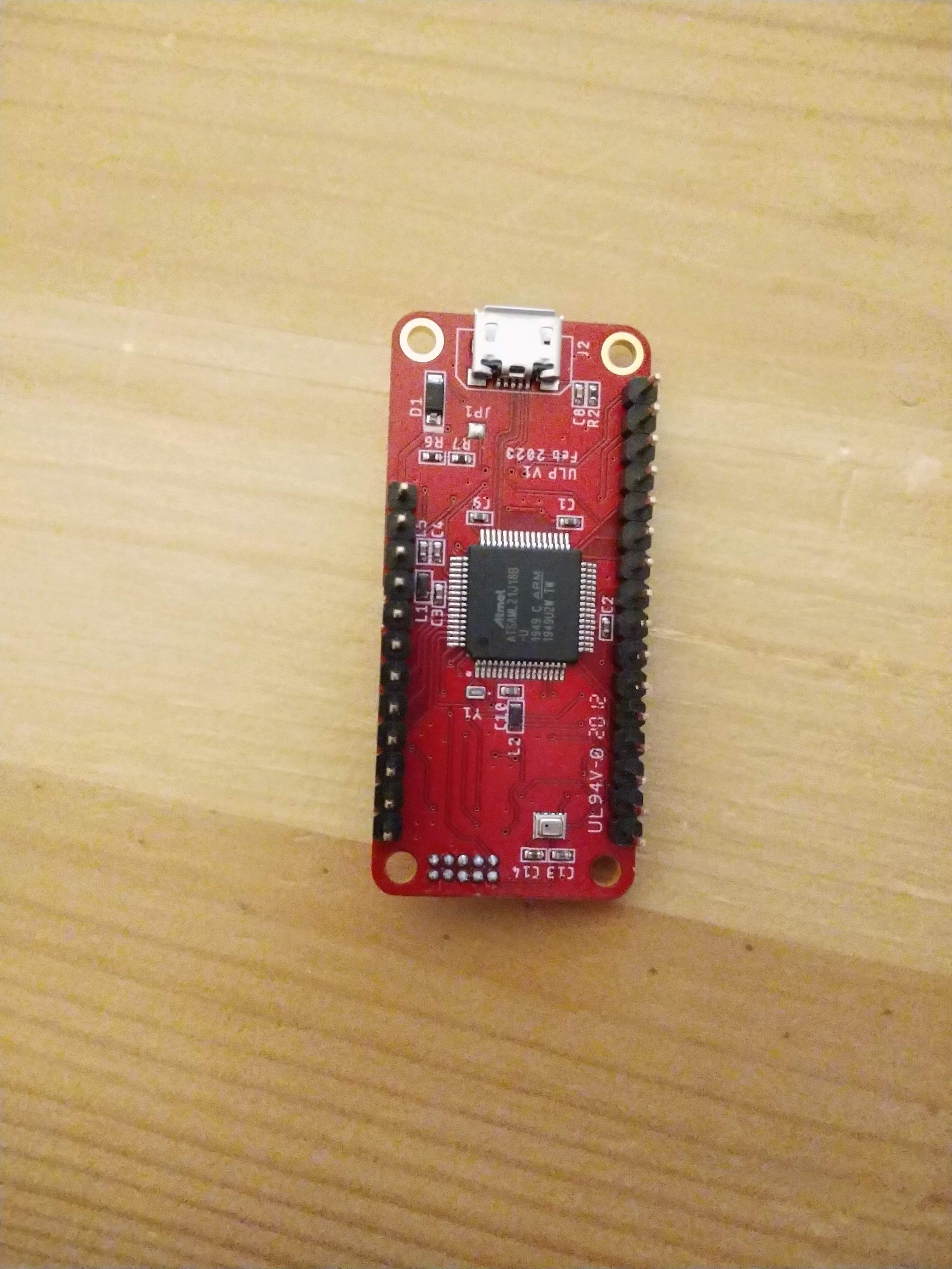
The microcontroller, barometer, and USB connector are on the opposite side.
The available power indoors is quite small, which is fine since this hardware needs very little power. However, unless the voltage from the solar panel is high enough, even trickle charging will not be possible. Therefore, even though the dual panels each have peak voltage high enough and we could have higher power charging with them in parallel, they are connected in series. This way, the hope is that more of the time the system will be able to charge.
Once I had firmware set up to interface with the accelerometer, barometer, and ADC, I started also testing power consumption in various operational modes. The ATSAML21 microcontroller is highly configurable and can run in a wide variety of modes, speeds, and with peripherals enabled or disabled. This makes it difficult to generalize power consumption. The marketing documents from Microchip claim <35uA/MHz, which I suppose is the absolute minimum to aim for. Within the datasheet however, this claim appears to not include any power used in clocks. It seems the minimum power clock is the internal 4 MHz clock. The firmware also sets up the ADC channels and an I2C interface to the accelerometer and barometer. I set up the firmware to cycle between active mode, idle mode, and standby mode for the MCU on a 5 second period. In all cases, the accelerometer and barometer were still on. With this testing setup I found the following:
- Active -- 285uA
- Idle -- 194uA
- Standby -- 9uA
In active mode, the MCU is running in performance level 0, using the buck converter. the datasheet claims 36-79/MHz in this setup in a while loop. The closest setup for the ADC listed in the datasheet estimates 89-120uA. The 4MHz internal oscillator requires 64-96uA. Based on the typical values, this predicts 297uA, fairly close to what we are achieving here.
The good news is that in active mode currently, the system requires 0.9mW. With any sleeping, the power is of course far lower. The solar cells each claim peak power of 26.3mW. It seems reasonable this system may be able to achieve continuous operation without sleep modes powered only from the onboard solar panels on indoor light.
Although the onboard 3.3V regulator was not usable, I was able to mimic the setup off the board on a breadboard. I tested the system with a 3300uF capacitor as the only energy storage. Note this is not a supercapacitor, and holds a very small amount of energy.
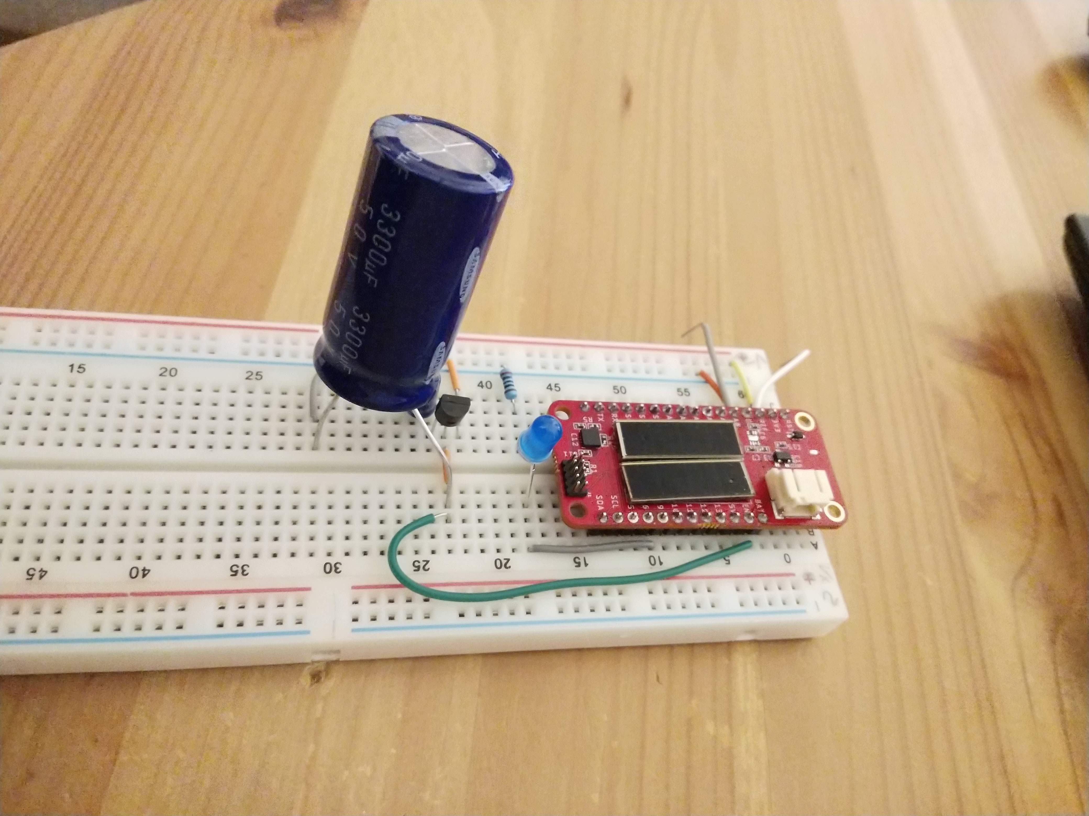
This setup in fact can operate continually from the power of a flashlight! With no power, it can run for roughly 20 seconds solely from the capacitor. The video below shows the LED flash while running. The flash is quite short since the LED requires roughly 100X the power of the rest of the system.
I have designed and ordered a next version. This next version has fixed the 3.3V regulator issue, added an ambient light sensor, and a small 0.33F supercapacitor for possible operation without a battery.
Discussions
Become a Hackaday.io Member
Create an account to leave a comment. Already have an account? Log In.