 Dominik Meffert
Sandprinting Test
Multi Material Test
Experiments with Sand, Powder and Clay Printing + Firing in a Furnace
Already have an account? Log in.
To make the experience fit your profile, pick a username and tell us what interests you.
Sandprinting Test
Multi Material Test
|
Standard Tesselated Geometry - 1.60 MB - 05/27/2020 at 03:36 |
|
|
|
Standard Tesselated Geometry - 844.81 kB - 05/27/2020 at 03:36 |
|
|
|
Standard Tesselated Geometry - 411.31 kB - 05/27/2020 at 03:36 |
|
|
|
step - 326.63 kB - 05/27/2020 at 03:36 |
|
|
Mounting Plate v2.stepYou can modify the mounting plate, so that it fits your printer.step - 83.52 kB - 05/27/2020 at 03:35 |
|
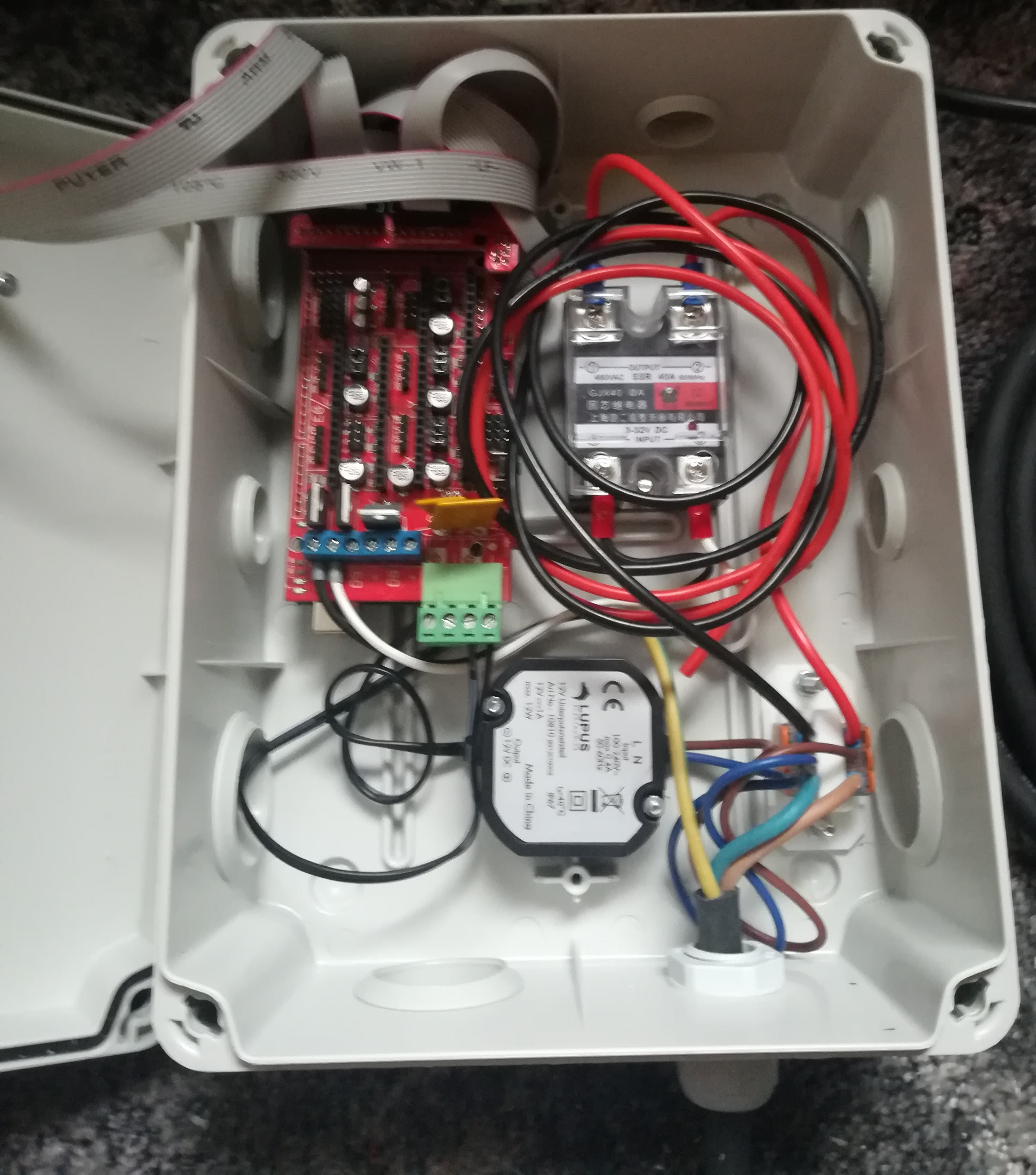
In the last few weeks I built a furnace together with a friend - He did the cutting and welding and I did the electronics.
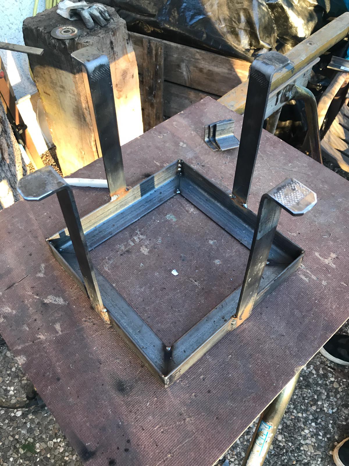
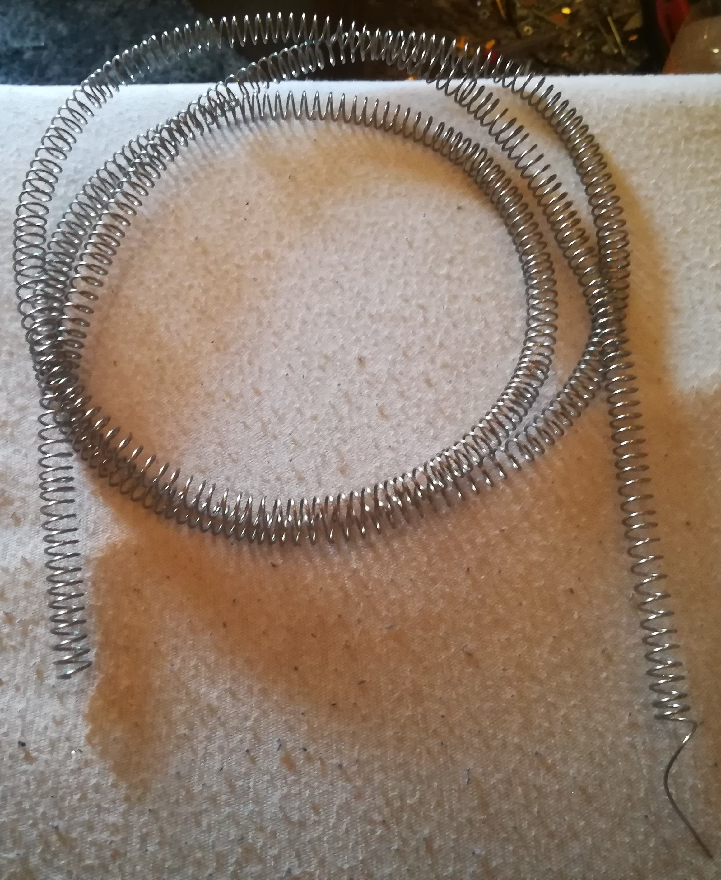
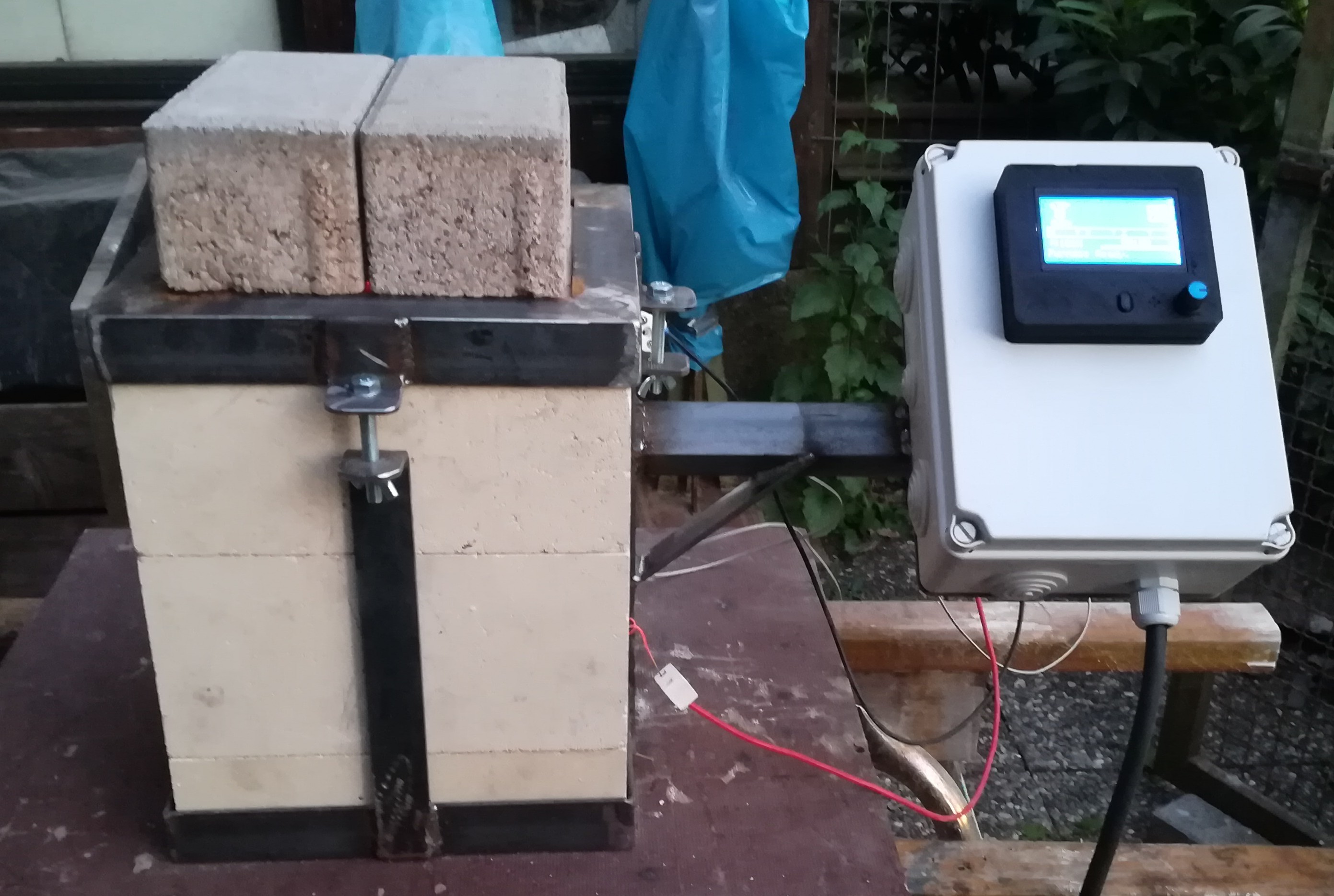
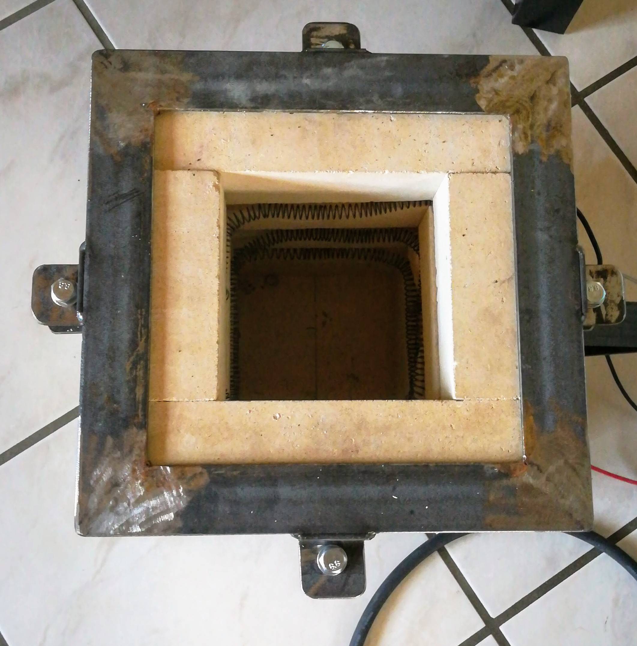
Yesterday we tested cooking something on it and melting aluminium.
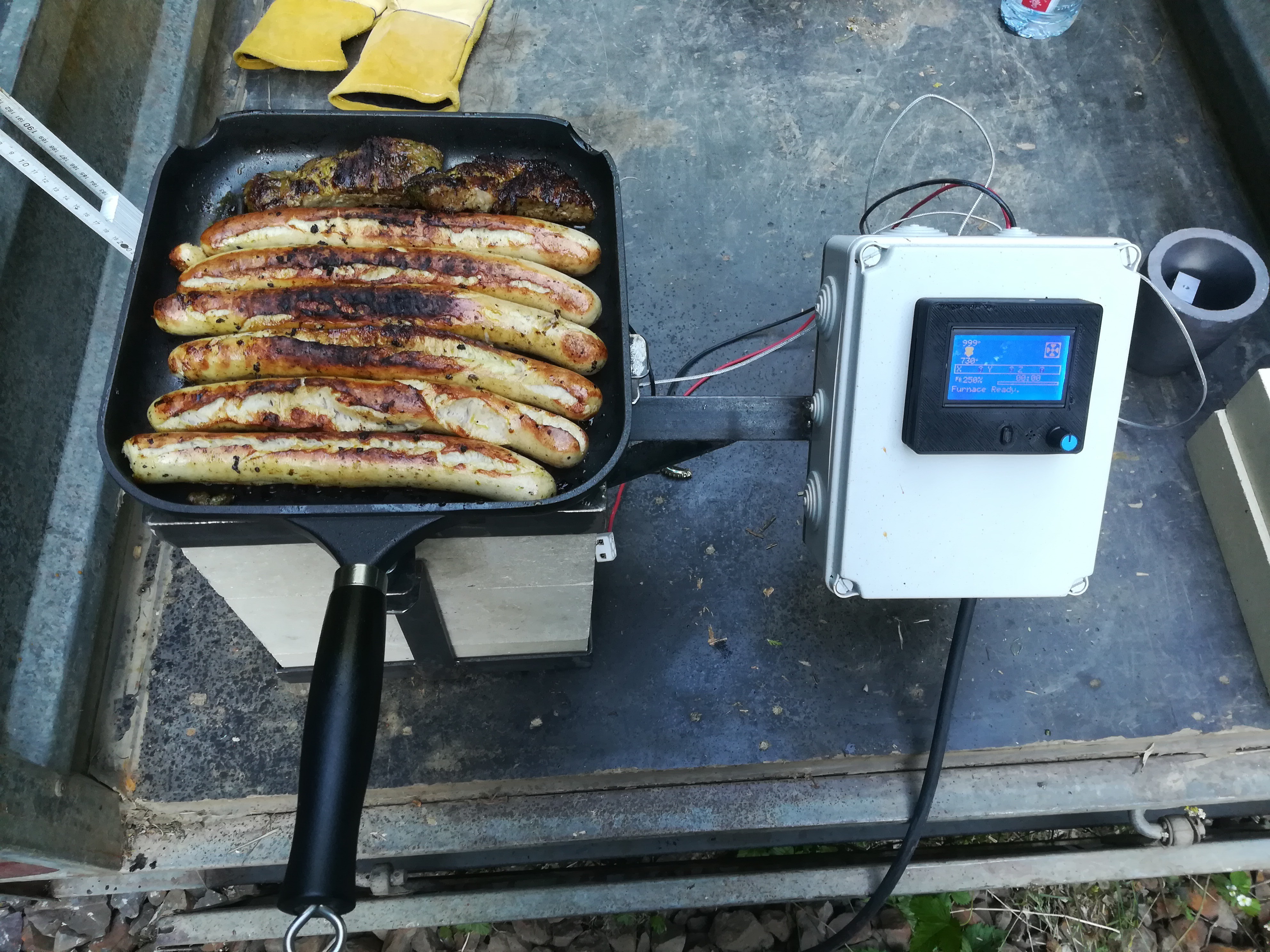
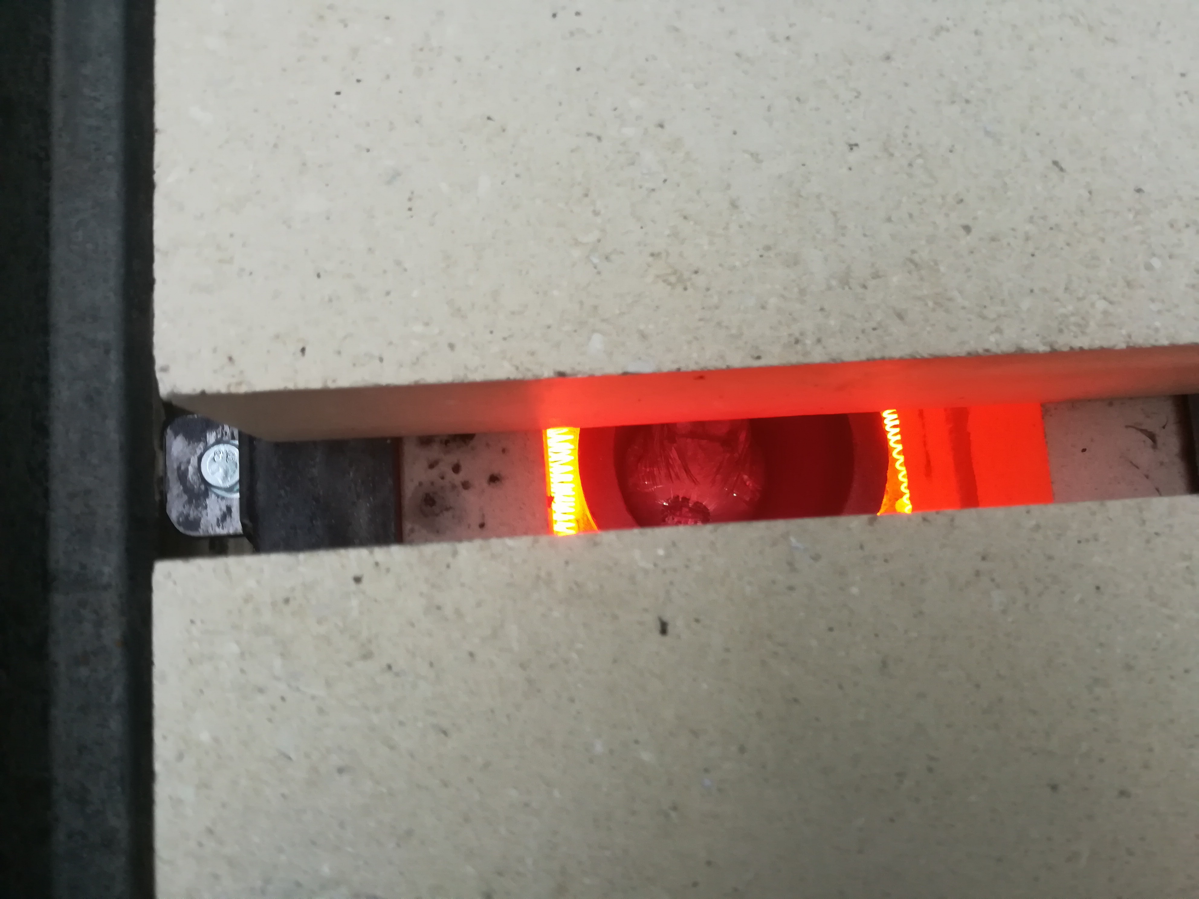
Both worked good, but it took some time to get the pan and the crucible to the right temperature.
I think the next thing will be building a clay and sand toolhead.
I read that clay is not a good choice for casting molds and so I will try to optimize the printhead for plaster/gypsum printing.
Update:
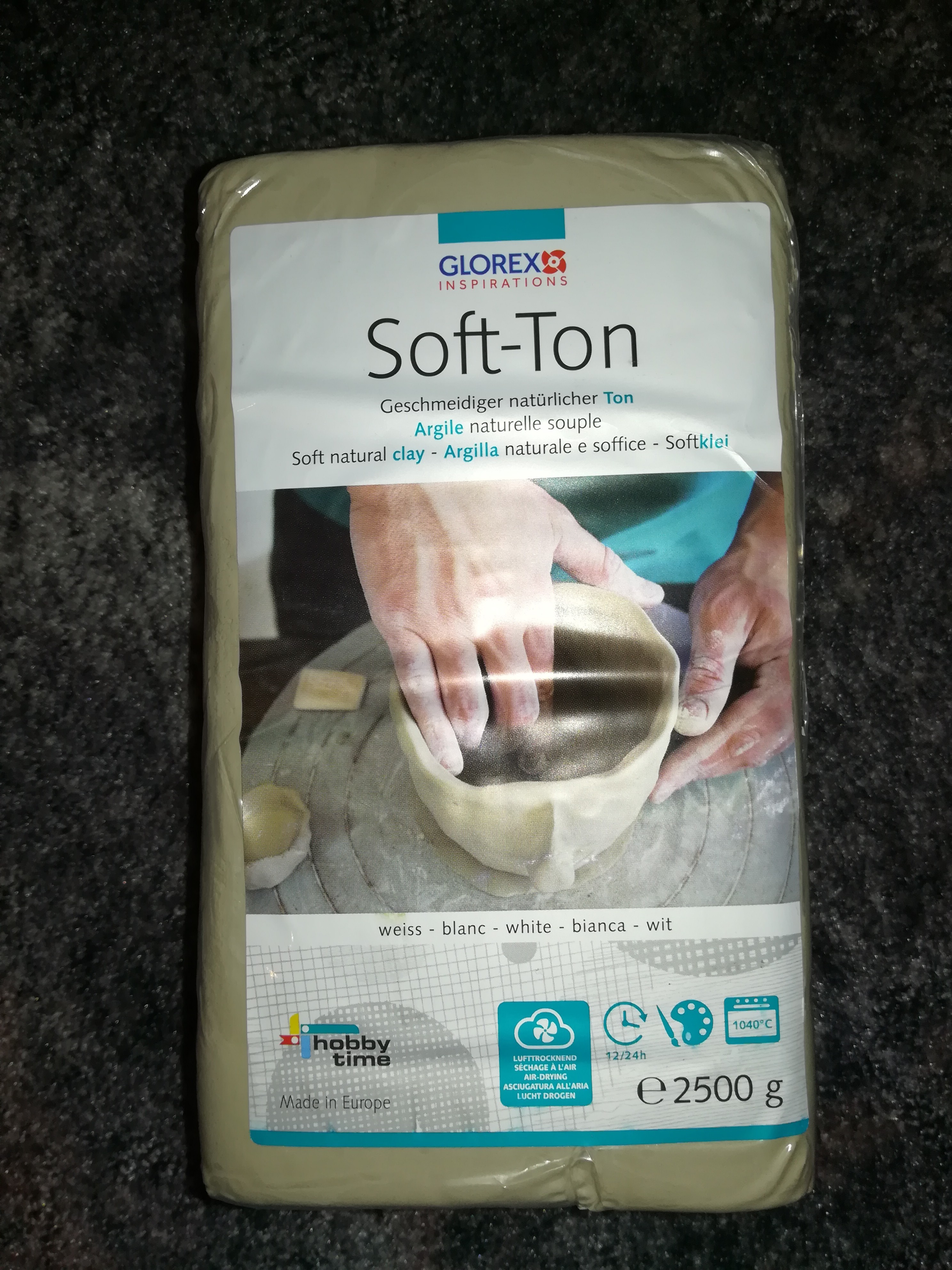
I tried casting plaster for another project and now I know that plaster stays liquid only for a very short time - So I think it is not suitable for printing with it and I will try out clay.
Ordered Clay for testing.
The Sand and Powder Printhead is ready for operation. I have uploaded the files that you can build it if you are interested in printing with powder material.
Next thing will be building a furnace, which should be done in the next few days.
I did a test with steel powder + sand. It turned out that purging in the ooze shield or a purge block is not the best way for changing the material. So instead of that I performed a 10mm Z hop at toolchange (which is a feature of the marlin firmware) to unload the rest of the old material in the nozzle before starting with the new material. If the feedrate is right there should be almost no material left. If the feedrate is too high, the amount of excess material is a good indicator which helps finding the right feedrate.
Actually it worked quite good besides of that the steel powder I used tend to clump together and get stuck after a short time...
I ordered finer steel powder and will test to move the inlet from 45° to 90° on the toolhead for a better material flow.
Update:
Tested the material inlet on the top. Sand works still good, but steel is still clumping together.
The new finer (<100 micron) steel powder got delivered today and it works way better, it also seems to be higher quality powder because there is no dust while handling it.
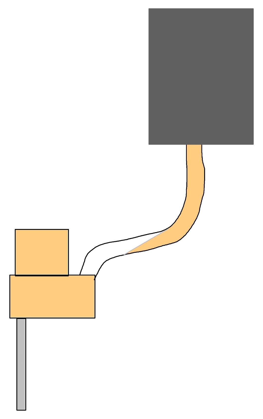
I did a single material test run and it worked quite good until the material "got stuck" in the supply line.
That happened because with the Z axis rising the supply tubes got bend and the material didn't longer fell into the printhead.
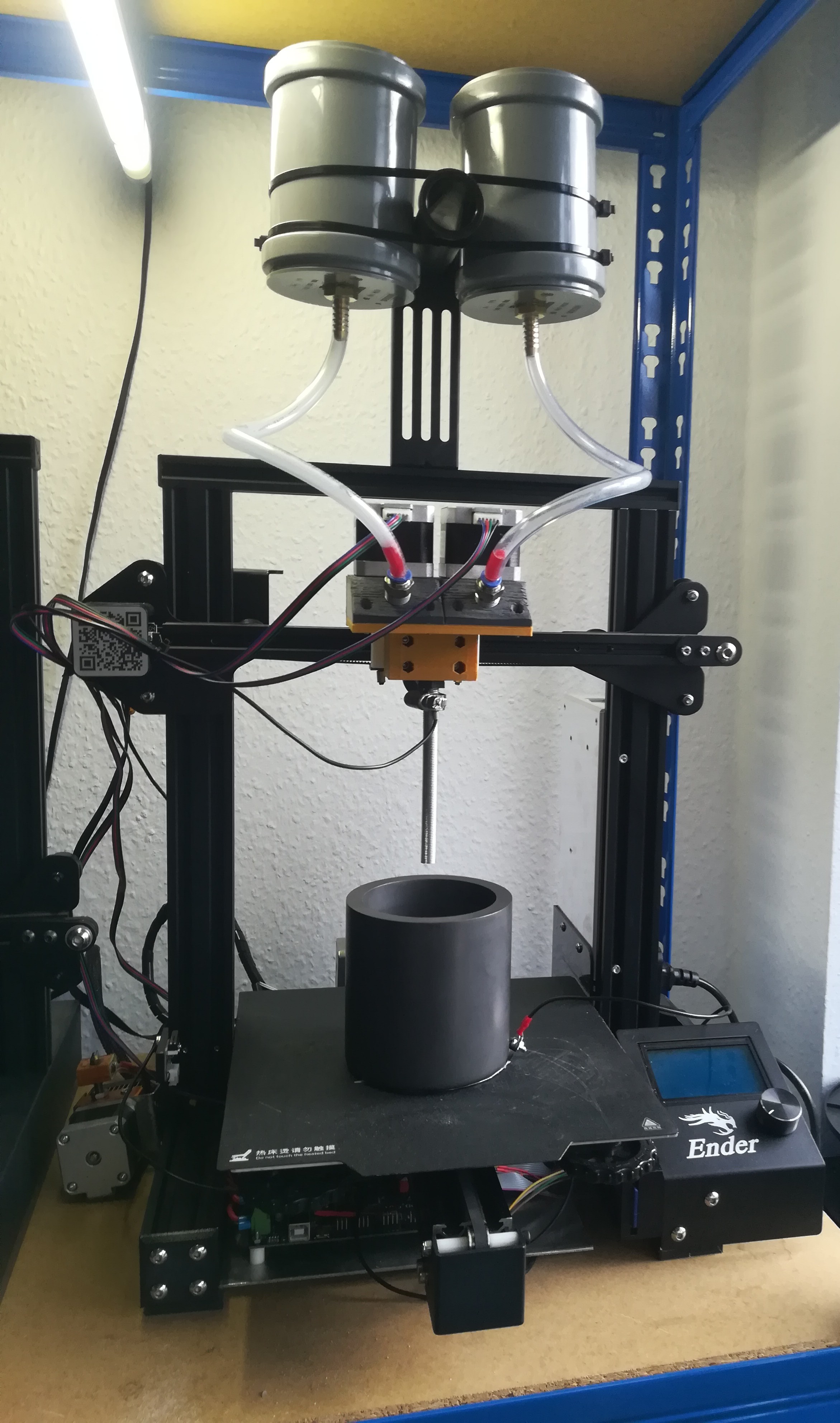
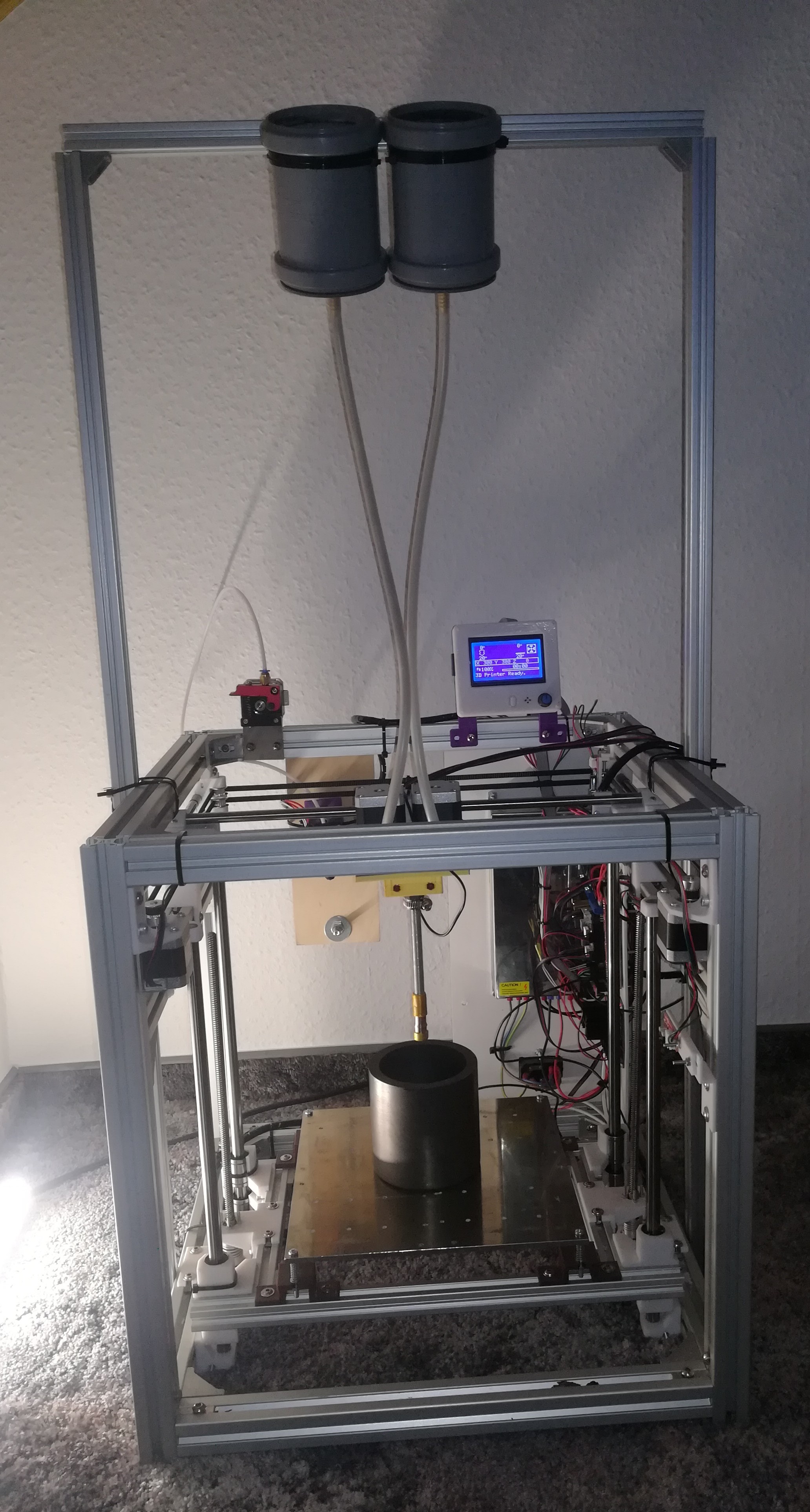
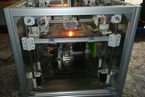
So I mounted the toolhead on another printer and added a frame with the material containers high above the printhead, so that the material can fall straight down into the printhead in any position.
Because of the G38 bug the endstops.cpp has to be edited to get it to work with a CoreXY printer.
In the file there are two lines from which
!(CORE_IS_XY)
has to be deleted.
The design with the material containers mounted high above works very reliable. I tested printing for several hours and never had problems with it again.
Because the printer should work with different crucible sizes to save time on smaller objects and because the printer has to know the exact limits of the build area it will use a probe to detect the exact position of the crucible center to use it as origin.
For doing so I connected a sheet metal plate on the top of the buildplate and the nozzle to the Z_MIN pin. Fortunately the crucible, that I'm using is made of graphite which is conductive, what makes probing it with the nozzle possible. It is necessary for printing and center finding, that the inside has a precise cnc milled U shape instead of a coarse V shape.
For finding the right point for start printing I use the following startcode:
G28                 ; home all axes
G1 X100 Y100        ; move to buildplate center
G1  Z150            ; lower Z

G90                 ; absolute
G38.2 Y150          ; probe Y+
G91                 ; incremental
G1 Y-1              ; for trigger open
G90                 ; absolute
G60 S1              ; save Y+
G38.3  Y50          ; probe Y-
G91                 ; incremental
G1 Y1               ; for trigger open
G90                 ; absolute
M92 Y40             ; set half the steps
G61 Y S1            ; move back only half the distance
M92 Y80             ; back to normal

G90                 ; absolute
G38.2 X150          ; probe X+
G91                 ; incremental
G1 X-1              ; for trigger open
G90                 ; absolute
G60 S1              ; save X+
G38.3  X50          ; probe X-
G91                 ; incremental
G1 X1               ; for trigger open
G90                 ; absolute
M92 X40             ; set half the steps
G61 X S1            ; move back only half the distance
M92 X80             ; back to normal

G38.2 Z0            ; probe Z-
G92 X0 Y0 Z0        ; set origin
In the Configuration_adv.h the following lines need a change:
#define SAVED_POSITIONS 2 //change 1 to 2
#define G38_PROBE_TARGET //uncomment
There is also a known bug on the G38 command which makes it necessary to set the probe pin in the Configuration.h, to get the probe to trigger on contact (Tested with Marlin 2.0.5.3). Do it with:
#define Z_MIN_PROBE_PIN 18 //use your Z_MIN pin
Because the printer needs besides changing the toolhead, replacing the controller with one capable of dual extruder operation and finding a place for the material no other modification, I think it's a good idea to use a budget printer like the Ender 3 Pro or similar to work with.
The only thing to watch out for is to use not too much acceleration in the Y axis to prevent distortion of the printed powder/sand layers.
The next thing will be finding out the startcode for homing and probing of the graphite crucible. I added probe connections to the steel rod and the crucible which will trigger at contact. The startcode should probe the crucible to find out its center (X0, Y0) and its bottom (Z0).
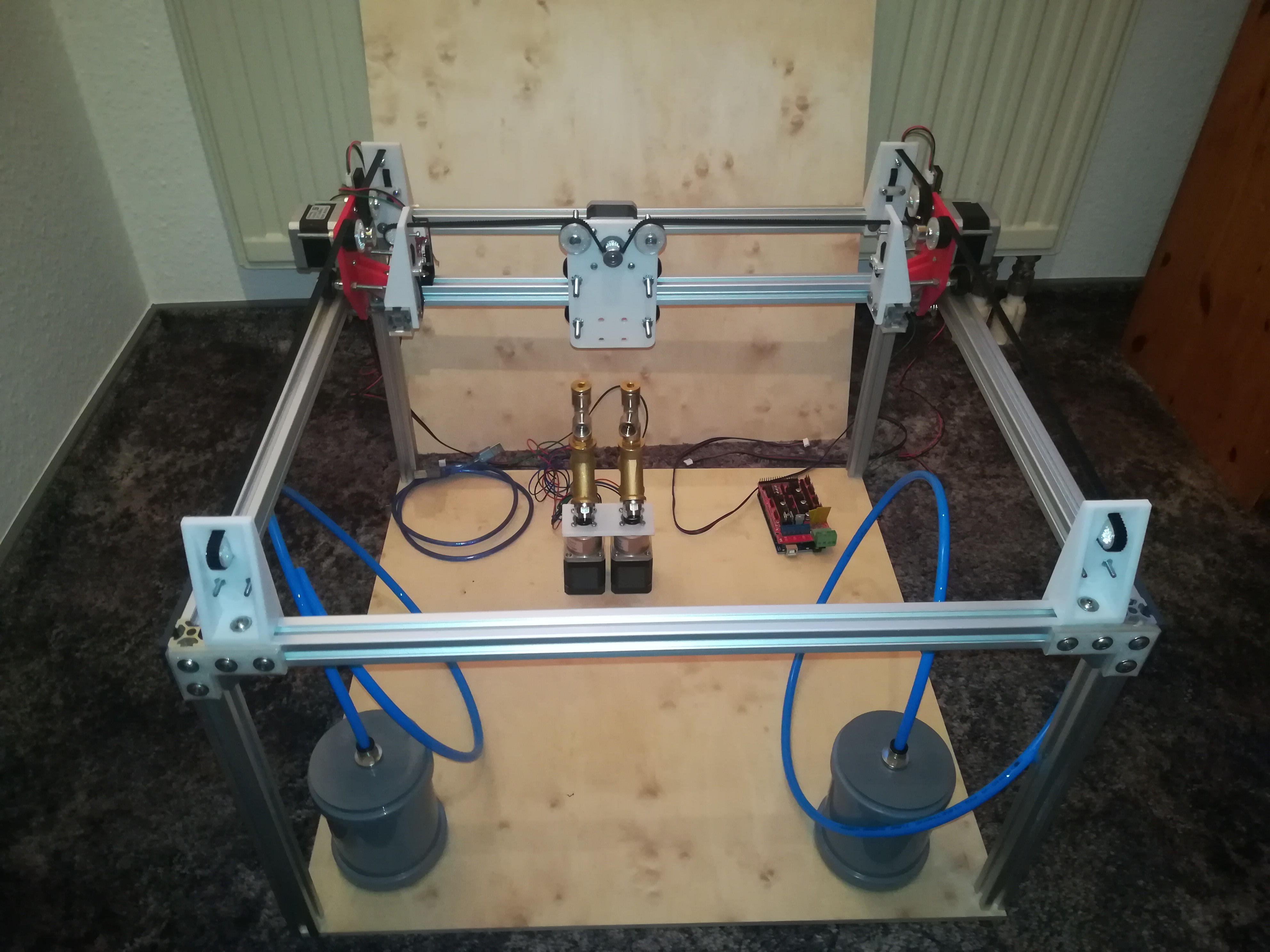
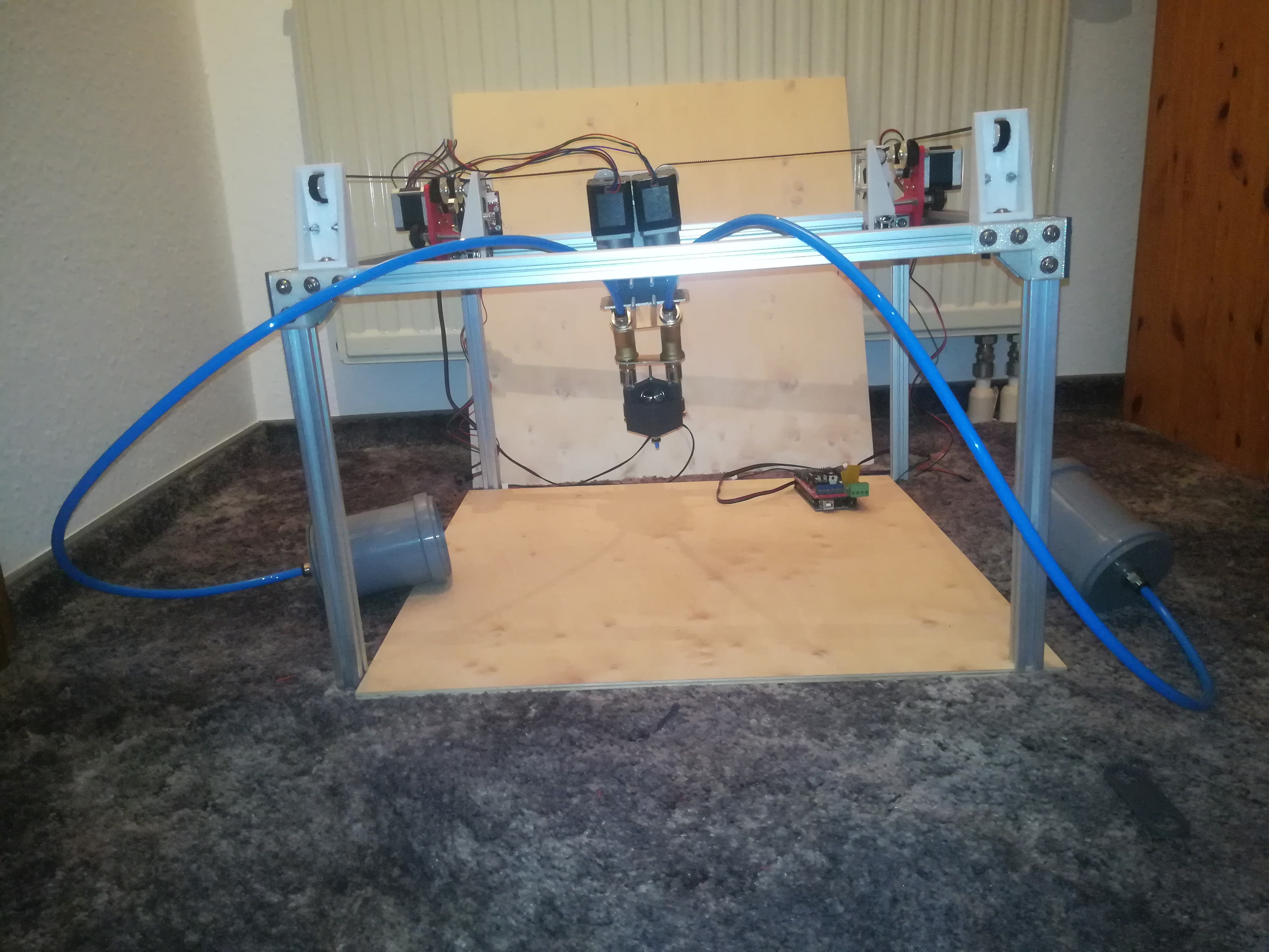
For testing the sand extruder I will build a 2D printer similar to my Inkjet Printer which should be able to draw two colored sand pictures.
If everything works, I can later add a Z axis to the bottom of the 2D printer print surface.
It should also be possible to print different materials with different toolhead setups like:
sand + sand for drawing pictures
sand + metal powder for metal objects
sand + clay/ceramics for clay/ceramics objects with sand supports
powder + laser for sls printing
powder + inkjet head for binder jetting
sand + glass powder for glass objects
Maybe I'm too optimistic and it will not work for any reason, but until that's the case I will share my experience with you.
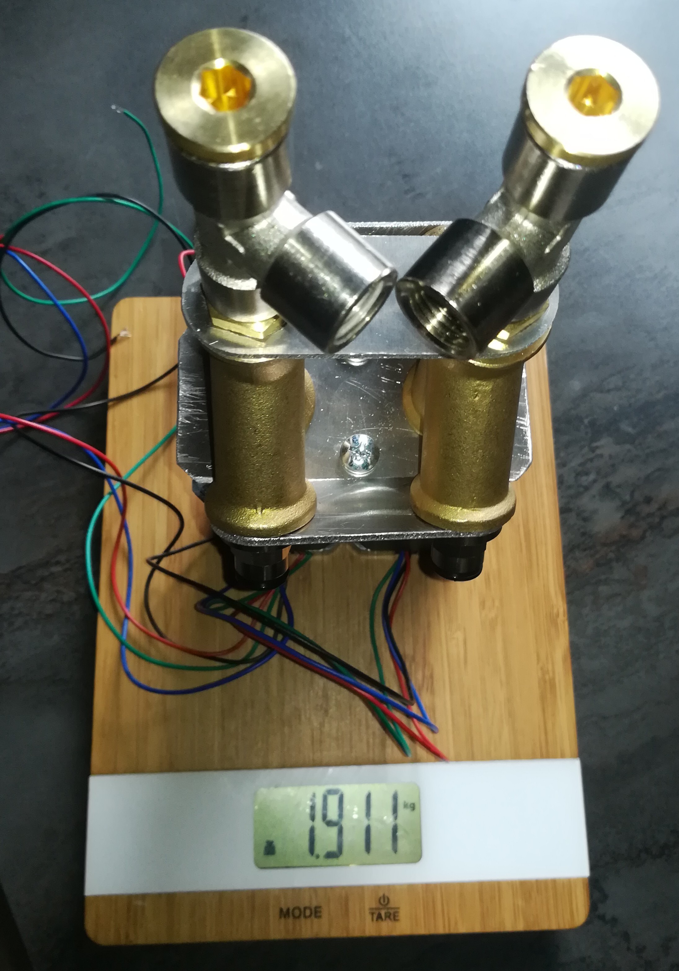
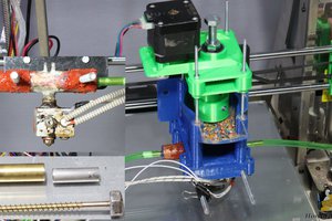
Multi Material Powder/Sand Toolhead
For printing with sand and powder I built a multi material toolhead, which should be able to print with two different materials without a toolchanging sequence through a single nozzle. This has the advantage that there is no second nozzle which could destroy the depositioned layer of material if there would be any height difference between the two nozzles. There is also no time wasted for a toolchanging sequence. It should work by doing something like "coasting at end" for emptying the funnel, which is the equivalent to the pressure - and in this case the entire material in the hotend - before starting with the other material. This should also happen before every travel move and should not add more time to the printing process.
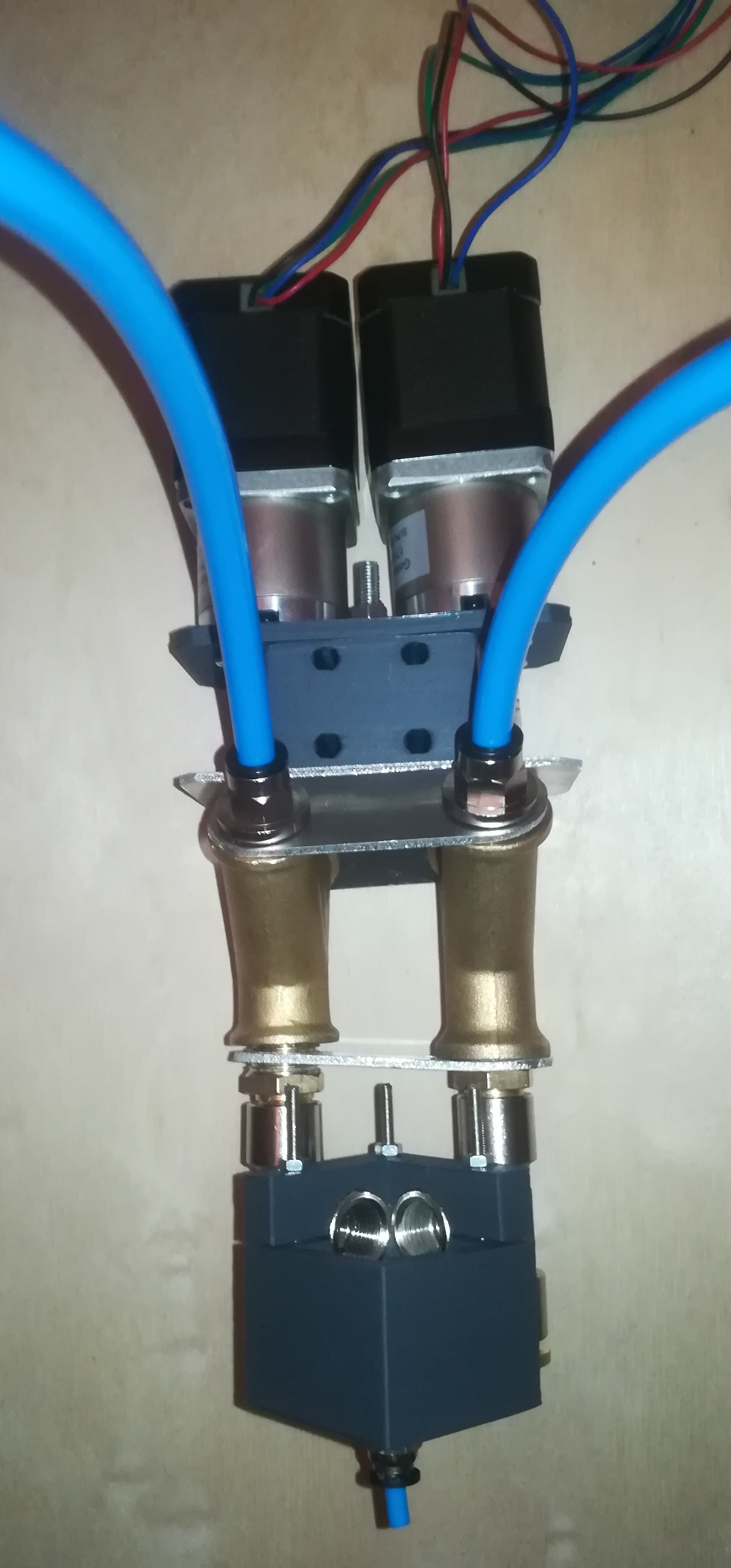
The only downside at the moment is, that the toolhead is quite heavy it weights about 2kg which will maybe require a heavier X axis for fast movements. The major part of the high weight comes from the two geared stepper motors which are necessary for driving the augers/drill bits which feed the material.
A test run of the toolhead.
A test run of the sand printhead. The flow is not steady, yet. For the next test I will look for a better auger to carry the sand.
Another test - This time I used a "normal" drill bit instead of a stone drill bit and the result is way better. Will buy another one to use both "extruders" in the next test.
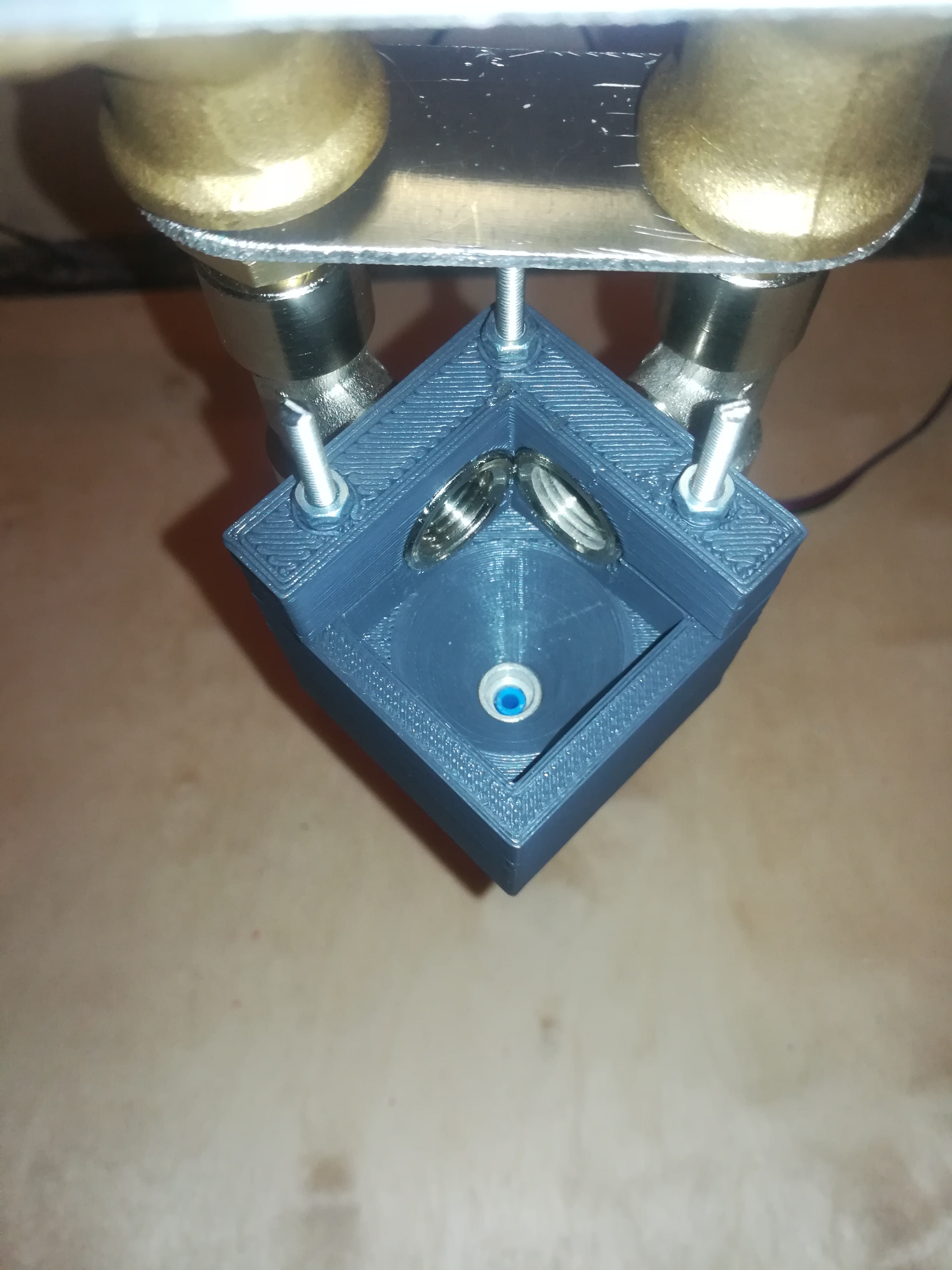
Because the auger based Powder/Sand Toolhead was not really reliable I designed a paddle wheel based toolhead which works way better.
The new printhead weights also less, what enables higher printing speeds.
With my metal 3D printing efforts I came across the Iro3D Printer (http://iro3d.com/)
which is a 3D printer which deposits fine and coarse metal powder + fine and coarse sand as support in a crucible, which later gets heated in a furnace and infiltrated with copper to create solid metal parts. I like the idea very much to create metal parts this way because there is no binder which needs to be removed and because after infiltration the printed objects are 100% dense. The only problem is the printing time. They say they need almost 24h to print the volume of the crucible which is quite long.
Maybe I can find a way to increase the speed of sand deposition for this project which also needs a lot of sand.
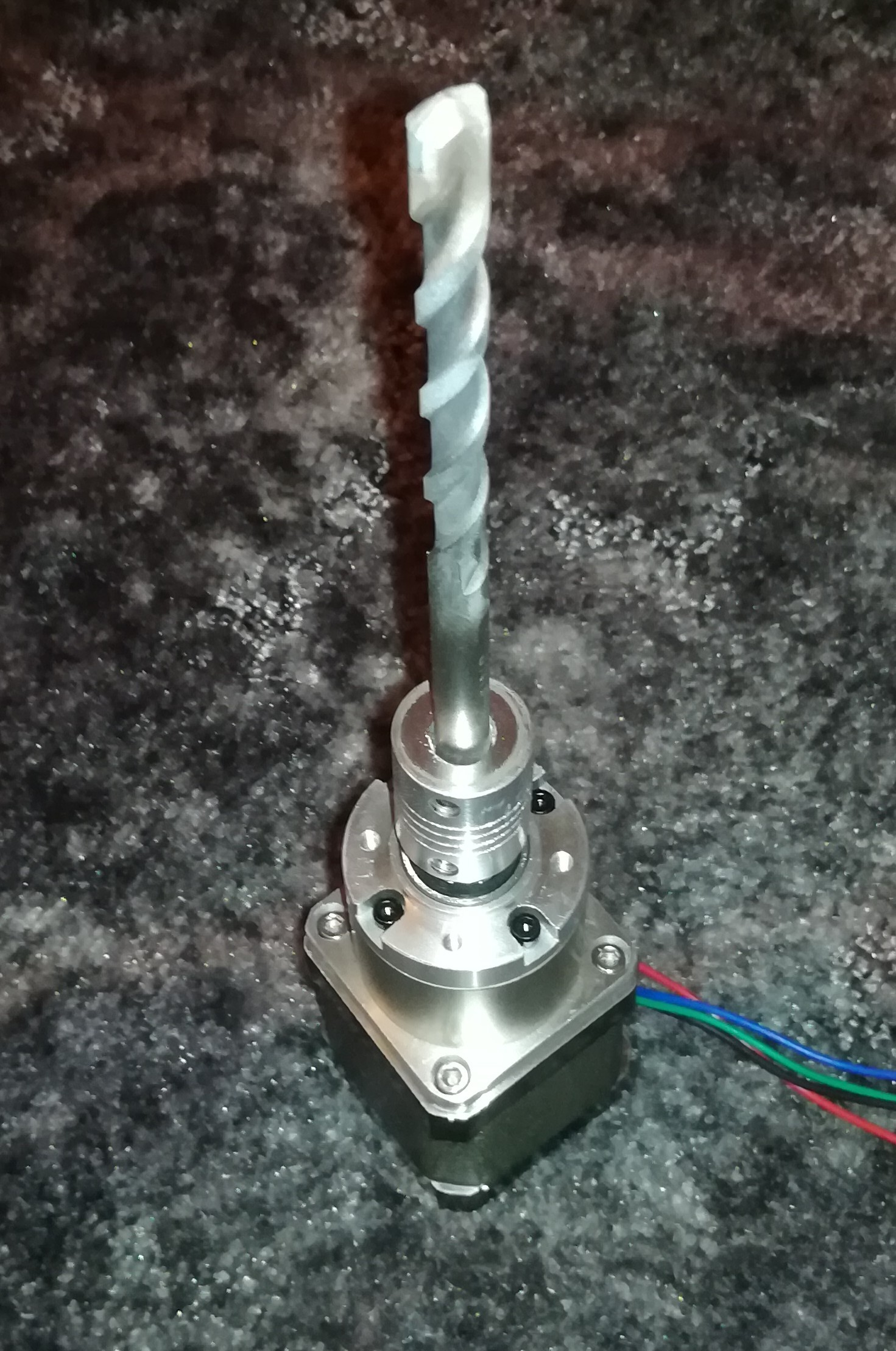
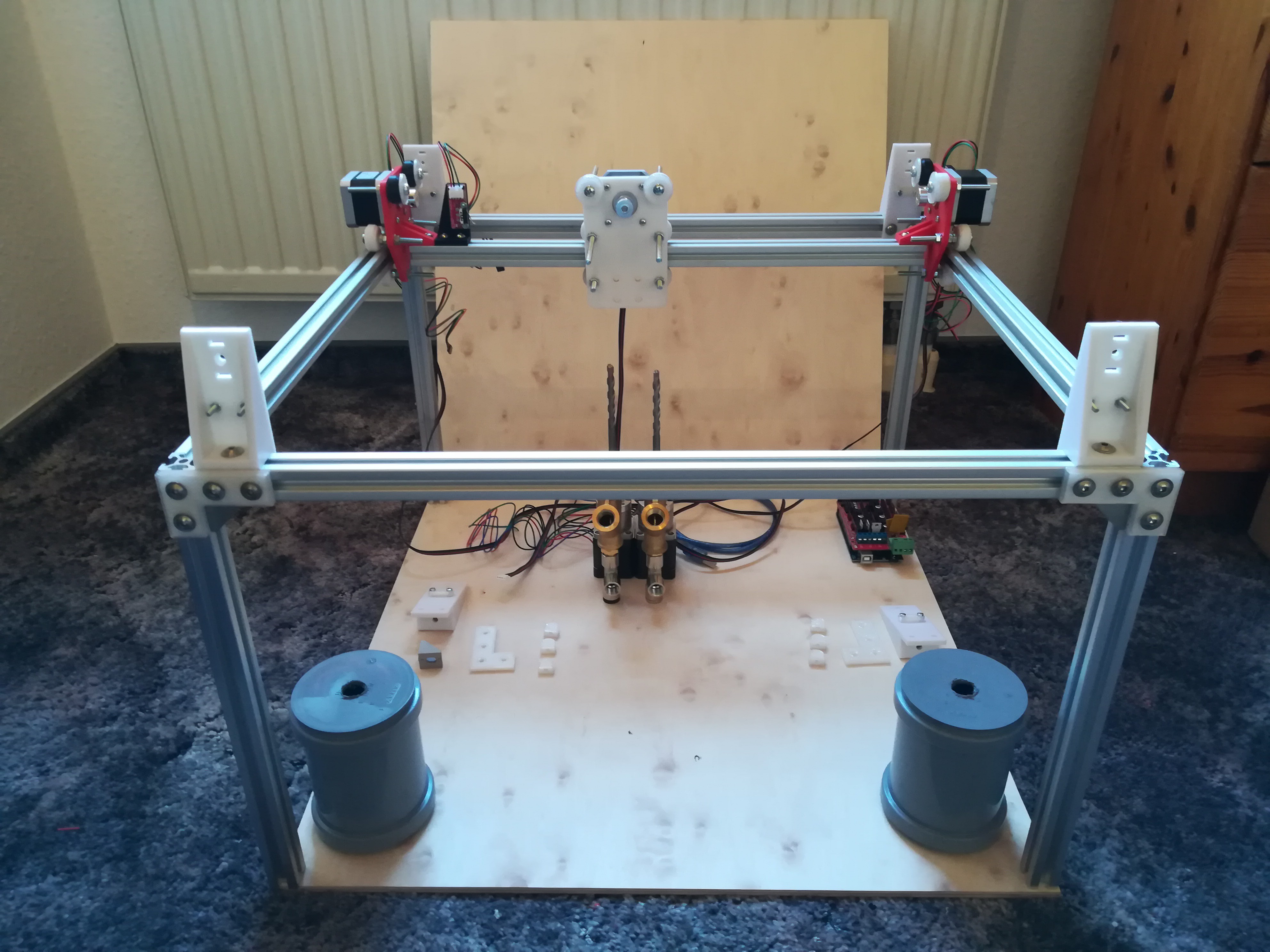
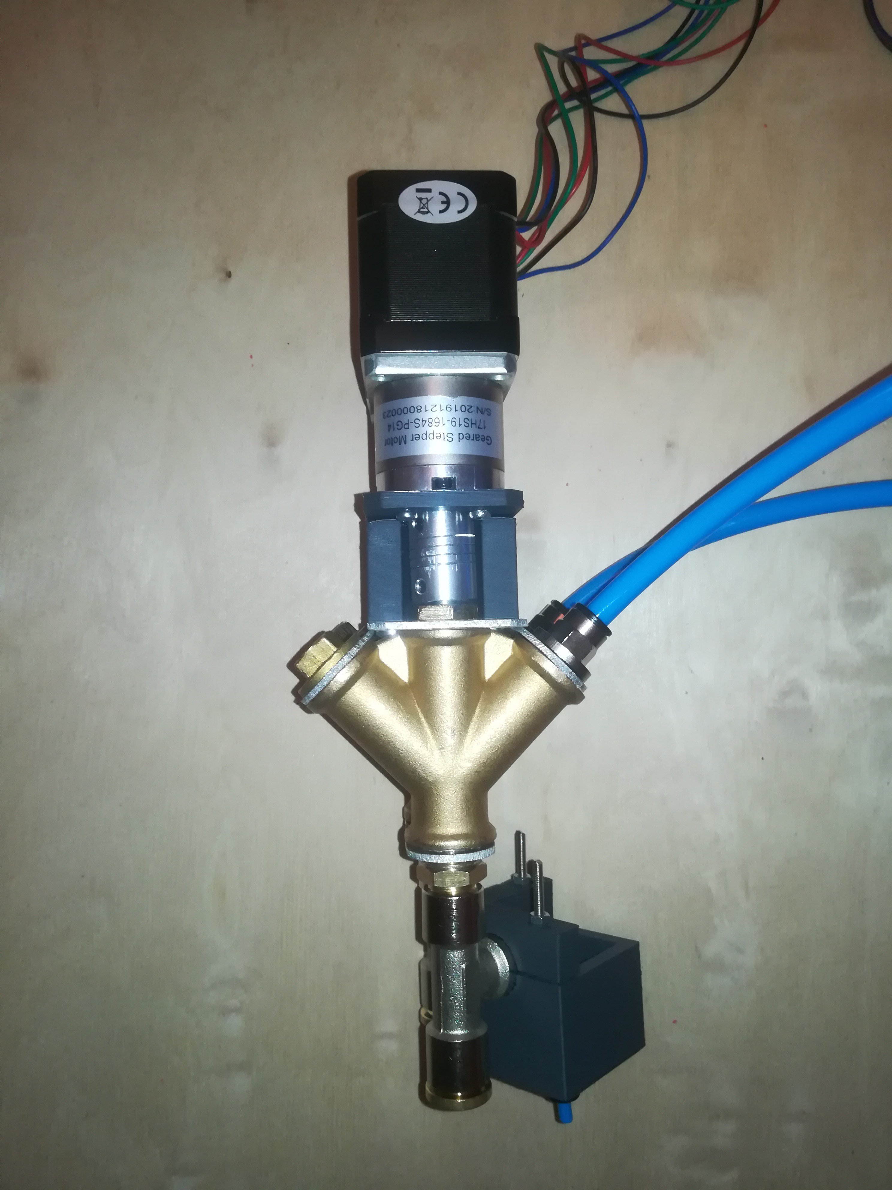
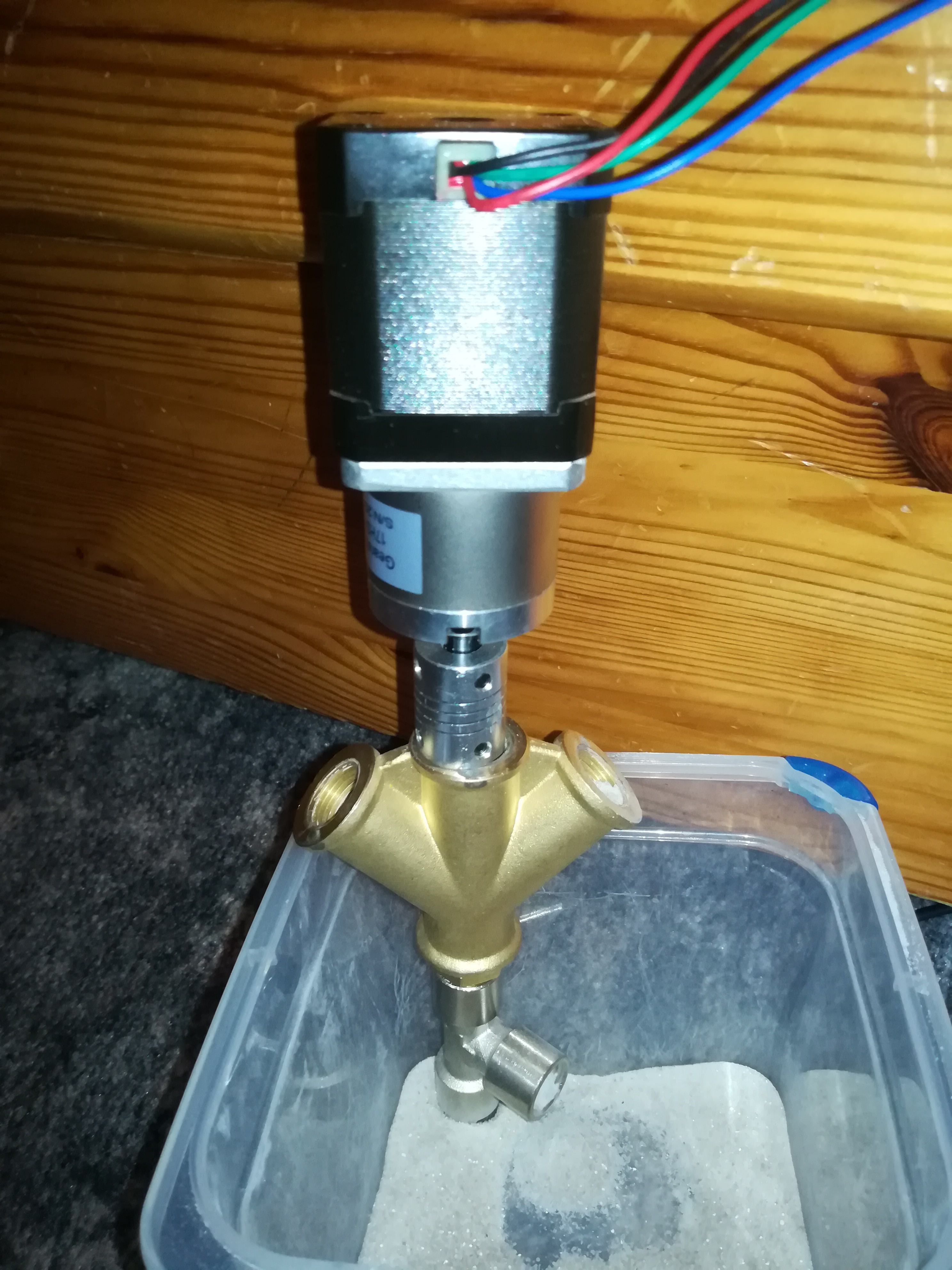
Test run of a toolhead which should later be used for printing sand or powder. The toolhead consists of a geared Nema17 stepper motor (14:1) which drives a 8mm stone drill bit and some fittings. There will also follow some 3D printed parts which will hold everything together.
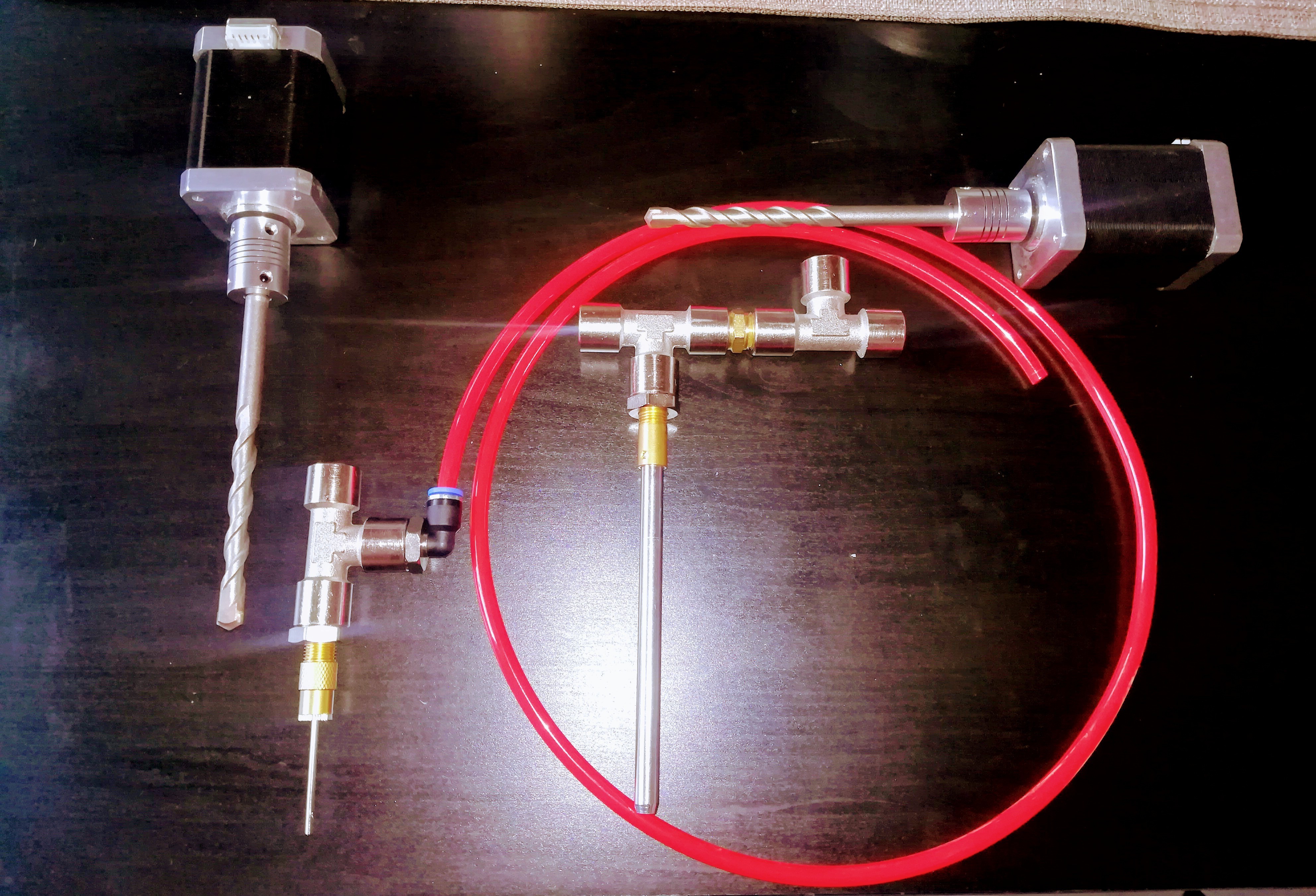
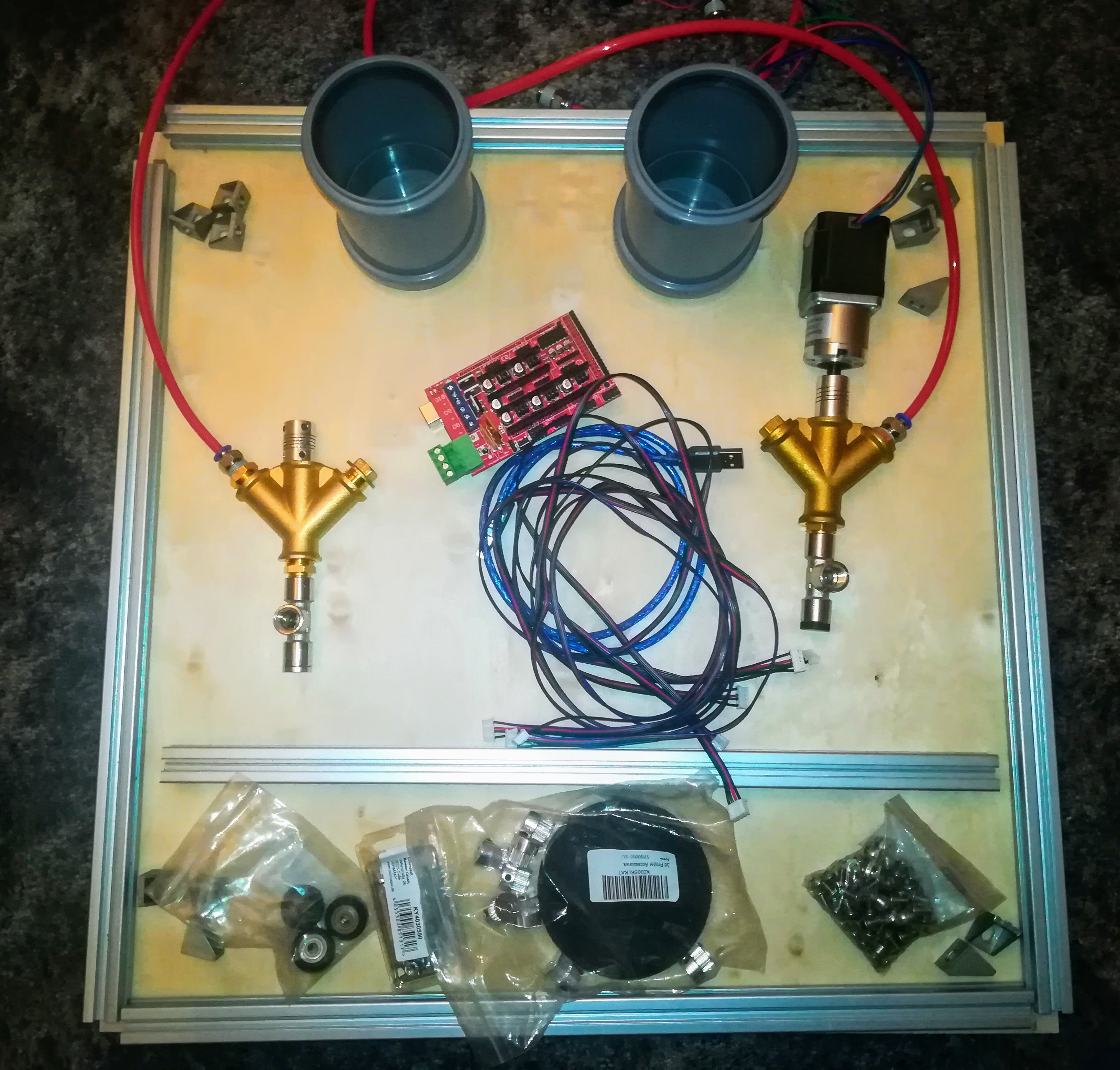
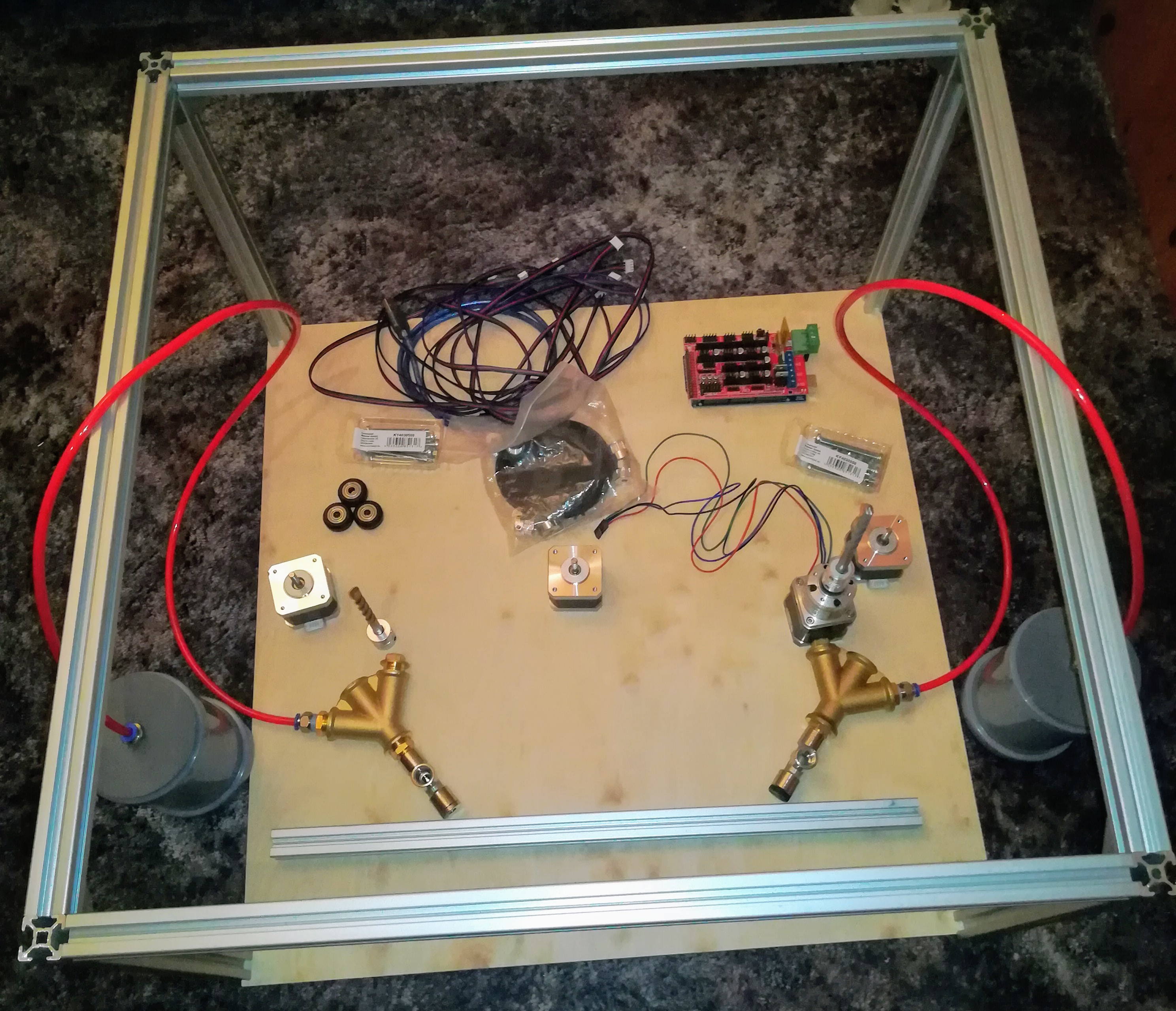
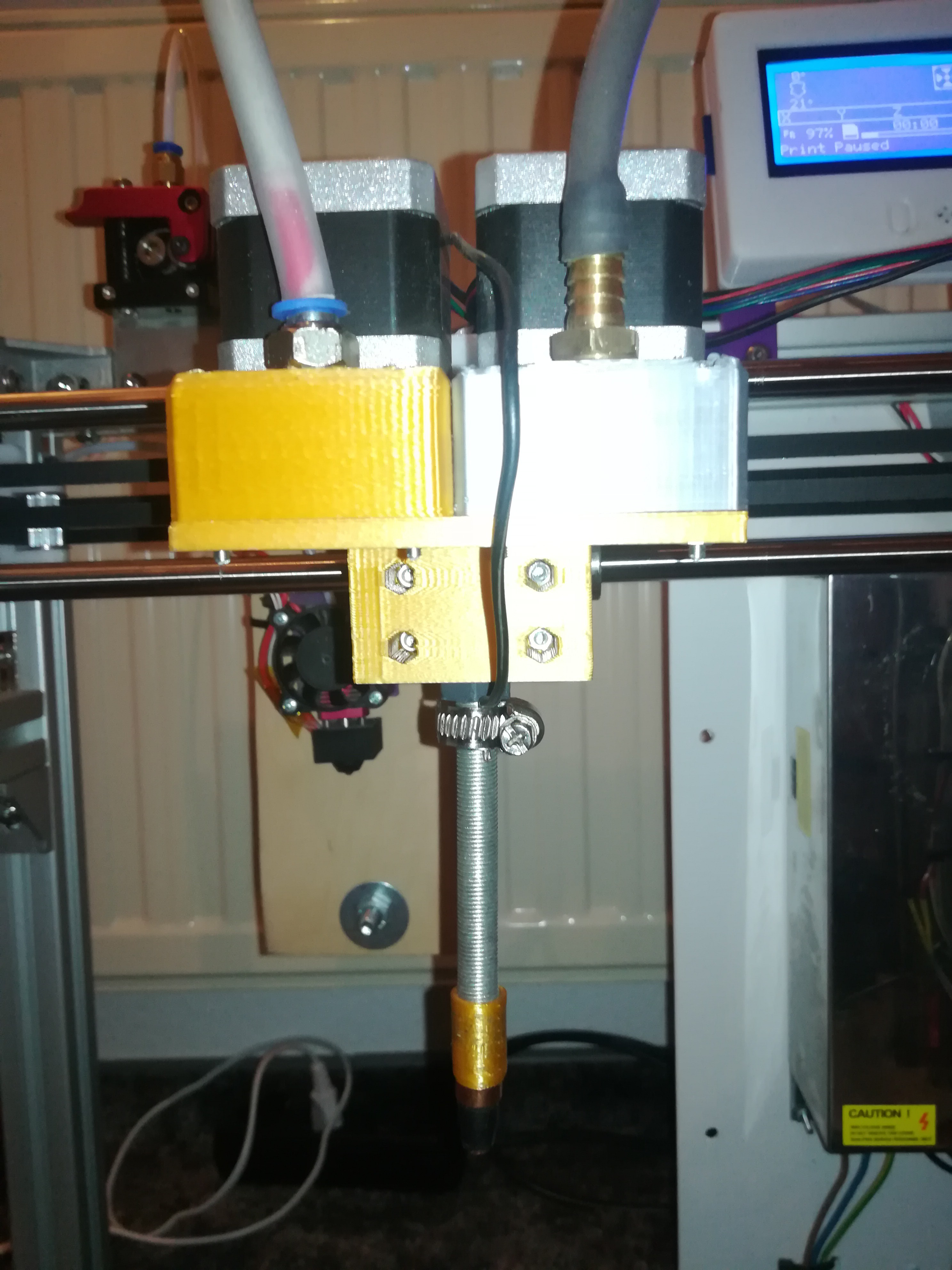
I bought some parts for getting started. The parts on the left should later become the clay extruder and the parts on the right should later become the sand extruder.
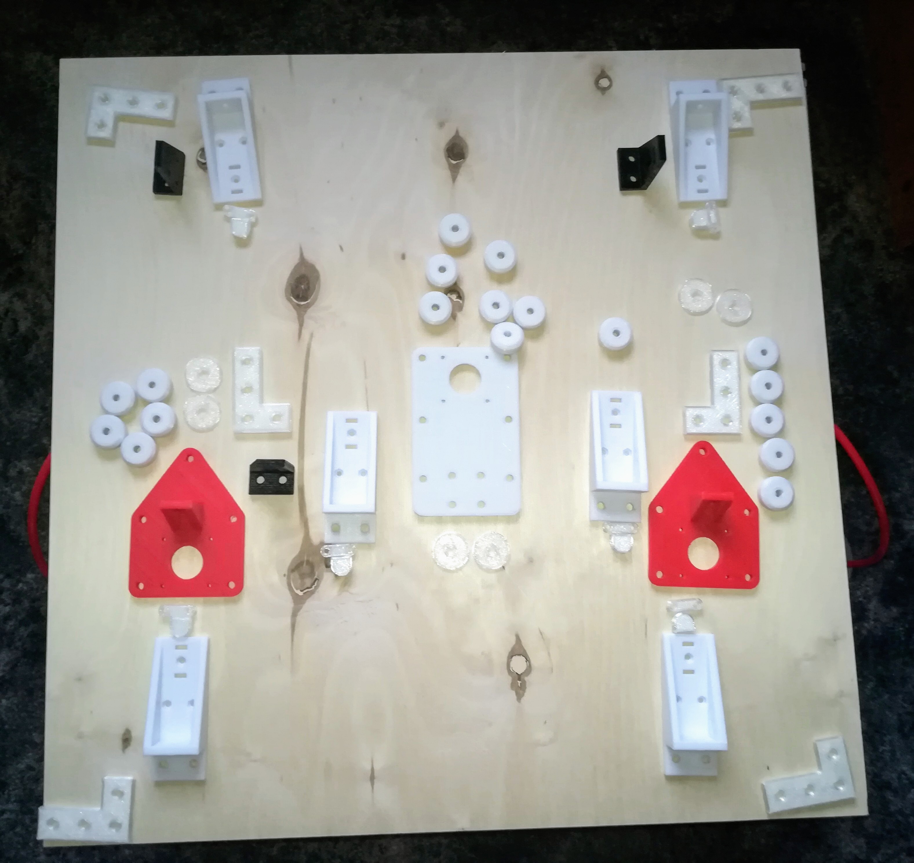
A few parts are still missing like 3D printed parts to hold everything together.
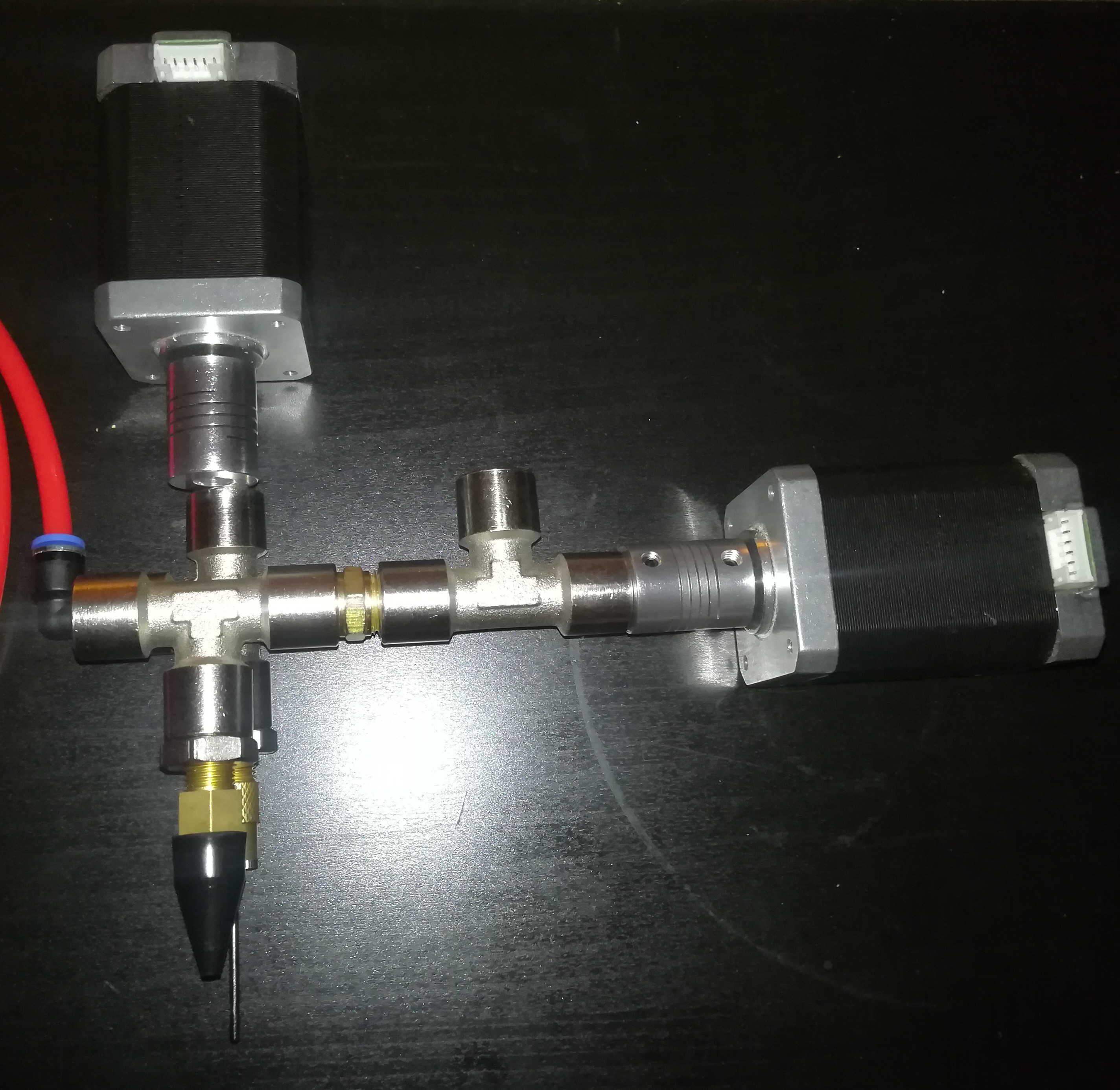
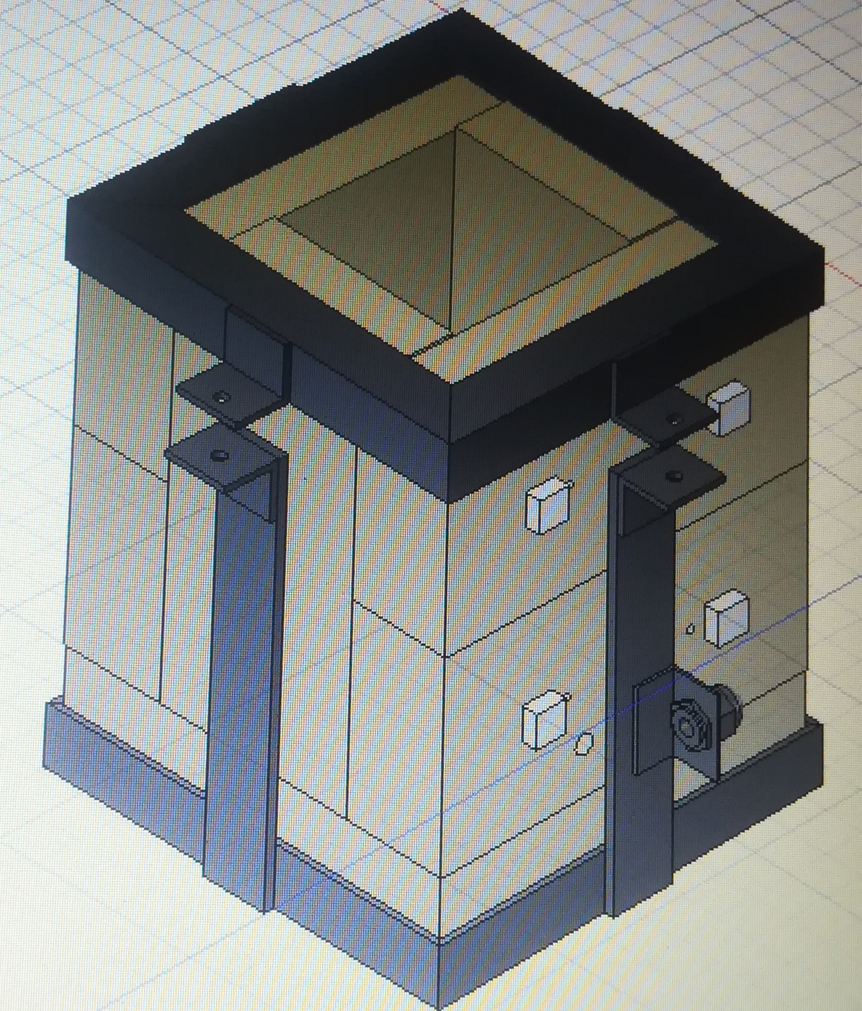
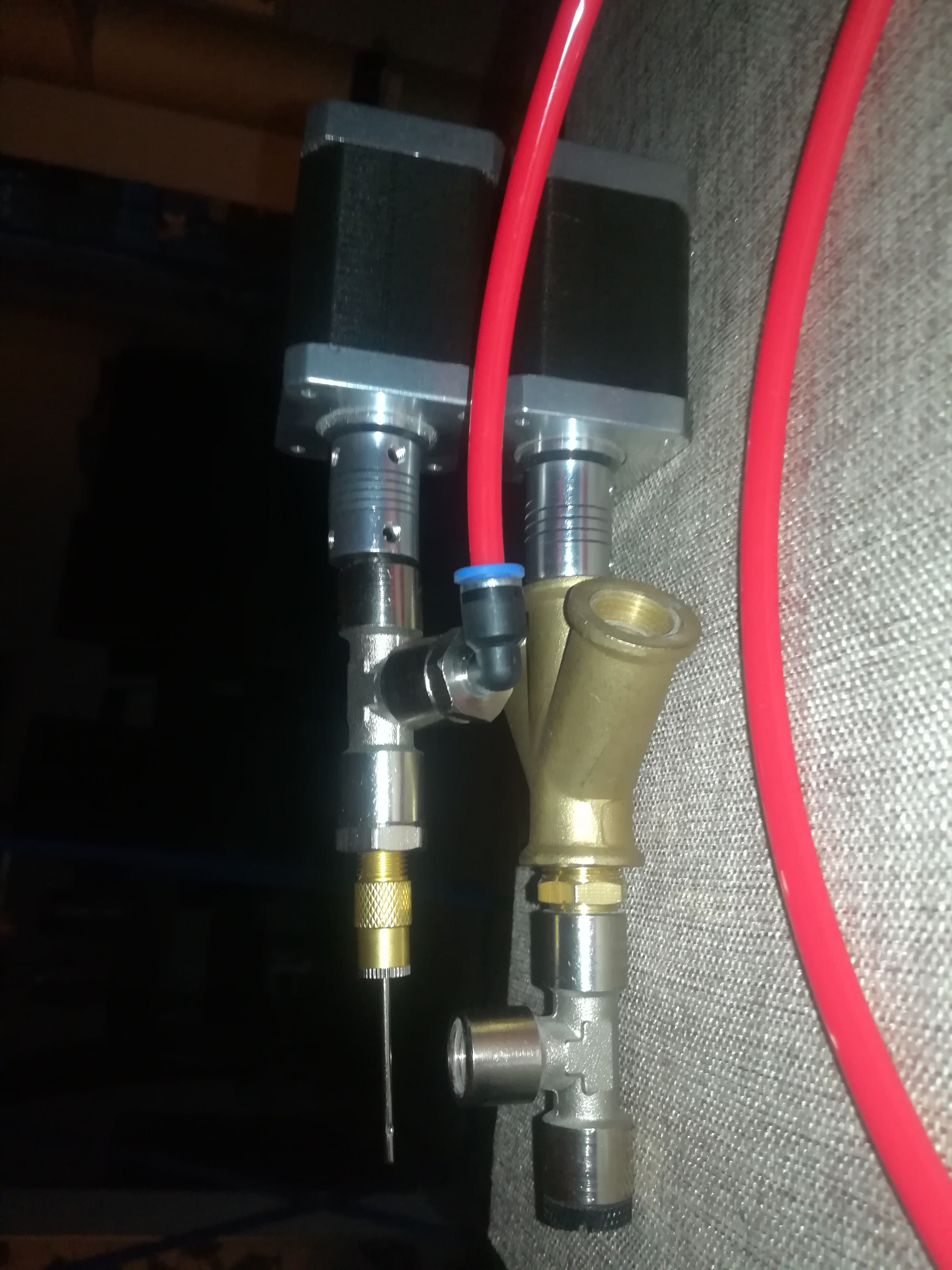
I found a way to use the sand/powder extruder in a vertical orientation to save a lot of space. The sand exits the extruder through the side port of the T fitting only when the drill inside is moving. I will also add a 3D printed nozzle to the sand outlet to bring the sand as close to the clay nozzle as possible.

also look into "Sodium Silicate" as a binder, it has been successfully used in sand casting foundry's.
Liquid sodium silicate is used as a binder instead of clay in the conventional sand moulding. The principle behind the CO2 moulding process is that when CO2 passes through a sand mix containing liquid sodium silicates binder for two-three minutes, it immediately gets hardened by silica gel formation. The silica gel (SiO2.x.H2O) is formed by the chemical reaction between sodium silicate and carbon dioxide. This silica gel gives the strength sufficient to eliminate baking/ drying of mould.
https://www.mecholic.com/2022/04/carbon-dioxide-moulding.html?m=1
Sodium Silicate becomes Glass.
Glass or molten beach sand is a crude flux used in crucible melting of metal because it floats on surface of molten metal and absorbs impurities while shielding inflow of atmospheric oxygen.
more process specific silicates might be researched like litho (lithium), and Alumino (aluminum), and ethyl silicates.
dental industry uses uv light cured silicates to form various in place ceramic fillings (commonly Fluoro Silicates (Fluoride)
grinding wheels are made using sodium silicate to fuse corundum into a pours solid grinding wheel.
Regarding preventing oxidation in plasma welding of metal powder, Take a look at using organic binders or binders which contain liquid flux. for precious metals, a commercially product called PMC (precious metals clay) (made in Japan) sold as, pure silver powder as a ready to shape clay, shape and heat then fuse with choice of methods, kiln, or torch.
similar techniques have been used throughout antiquity by artisans of Pharos, Czars and Kings in the process of "granulation" which is many, micro spheres of gold decoratively and carefully arranged being applied with a tacky liquid formulation (glue) to the surface of a gold object, then the artisans used their skill to carefully fire the object either with blowpipe flame or kiln. thr skilled goldsmith was able to compensate for the reaction of the binder swelling and subsequent contracting which occurred just prior to the granulations fusing to the metal surface without any evidence of micro spheres being disturbed or displaced at end of process.
All of this brings to mind the method of growing synthetic sapphire developed by a man named "Vernuil" almost 140 years ago, "Verneuil process" , also called "Flame Fusion" involves an Oxy-Hydrogen fueled torch where the flame is directed downwards against a slowly revolving refractory pedestal whish is incrementally lowered usually over a time duration of several inches per day. for growth of sapphire or corundum, Aluminum Oxide powder is supplied "in-situ" (in place) vibrated or shaken consistently from a hoper and tube directly within the flow of gas and emerging within the super hot flame itself.
Every oxygen/fuel flame can be proportioned to create either oxidizing or reducing atmosphere at the site of the flame. It is an excess of fuel gas which checks or prevents oxidation at site of fusion when welding metal with a torch. although outside of the welded interface surface metal often oxidizes then a metal worker typically uses acid pickling or abrasion to clean the metal.

I like this idea - if I understand it correctly, that is. My worry would be that the co-extruded sand or powder support would have a drying effect on the clay, sucking moisture from it too quickly. That might be fine - in fact, it might even be beneficial, almost like pre-curing it before final baking. It seems like something that would just need to be optimized.
Looking forward to seeing this developed!

Hi,
maybe I could try different sorts of sand or powder to figuring out the best material for it. My biggest concern at the moment is the printing time, because the support material has to fill the whole empty space at every layer what could take some time. Maybe I could get around this by using print chambers with different sizes - smaller chambers for smaller objects and larger chambers for lager objects.
 Norbert Heinz
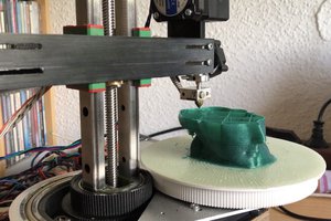
 heinz
heinz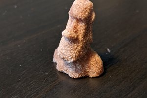
cool project . A few years back there was a commercial printer with was printing with this idea. But it didnt materialze