 Pierre-Loup M.
All panels of the synth are made out of acrylic sheet. I believe other materials would be nicer, but it happens I use 4, 6mm cast acrylic, and 2mm extruded acrylic sheets for work, thus having plenty at hand.
And as I'm lucky enough to also have a laser cutter, it became an obvious choice to use acrylic, that I can both cut and engrave in one go.
The front panel, despite its simple appearance, took time to design. It had to be decided all the function wanted, were to place them, take attention to the room around switches and potentiometers (for moving them AND regarding their own size).
Then space them evenly, and check... to move them once again, because something was missing... A game of try and error. :)
I also used a scrap piece of acrylic to place buttons on it to have a real idea of how it would be, and check distances.
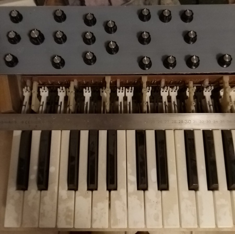
There is some dust here...
I mainly use Catia V5 for everything I need to design. The panel has been drawn in Catia, then a layout exported to DXF. The graduations for pots, waveforms, texts, separations are made using InkScape (which has powerfull tools for spacing shapes). In fact it could be design with InkScape alone. The file is then exported to DXF again, and the laser G-code generated using CamBam (which, despite its Windows 95 look, is a great tool too !)
I wanted to have more controls on the panel, but the keybed dictate its size, as well as the available inputs on the Arduino Mega. I wanted to have reverberation and / or delay, but not enough room. And as it's now, every single ADC on both Arduino is used.
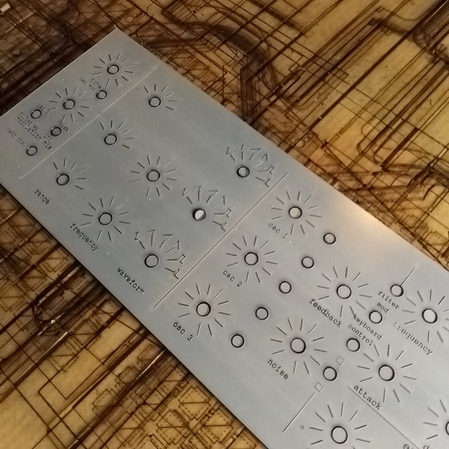
This is the first panel, I then realized some things had to be moved, other added...
Once the panel cut-out, engravings have been filed with white paint. it's quite straightforward : a lot of paint is put on, then the excess is wiped out.
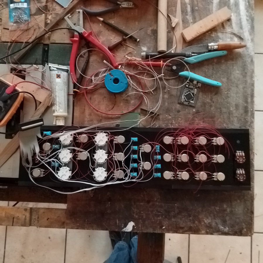
The controls have all been mounted on the panel. They are mounted with shims, to compensate for the switches, potentiometer and selectors height, to have the controls at the panel level.
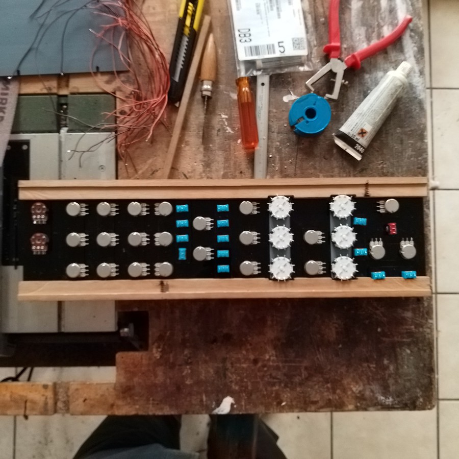
Potentiometer are all 10k linear, except one (two on the picture) for output and headphone levels, which are logarithmic ones. (Side note : it needs an amplifier to buffer the phatDAC output, which I don't have yet. Don't even know what to use !)
They are all wired to their respective ADC on one or the other board.
Switches are all two position ON-ON, except the one for octave control which is a temporary three position (ON)-OFF-(ON). They are wired one pin to digital inputs of Arduinos, the other to GND. Every switch uses internal pull-up resistors of the Atmega.
Rotary selectors are connected to ADCs. Their first pin (position 1) is grounded, the last pin (position 6) is tied to VCC, and a resistor ladder is soldered on the pins in between, so the output is stepped evenly between 0 and 5V, and only one pin of the Arduino is needed per selector. The wiring is also a lot simpler compared to what it would be with digital pins.
Note : I may draw a general wiring schematic, but all connections are listed in their respective sketch, and the github repository has a file listing controls, and two for front and side panel connectors.
I started by wiring everything to ground, then VCC (which is 5V here). I didn't really think about how it should be done. I've taken care not to create loops, but it has been wired as it came.
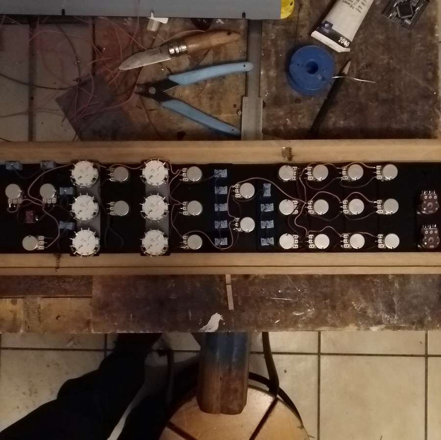
The last step is to wire all the signals. I used a 34-wire ribbon cable from an old computer, which connected perfectly with a shorten Raspberry Pi GPIO connector. And it was long enough so I could reach everything in the panel with the connector mounted on one side. So...
Now it starts to be a mess !
The second Arduino Mega is mounted on the rear side of the front panel, with double-sided tape.
The panel is held close by screws holding the back, but I'll come back to it later. On the picture is may be seen some marks on the wooden parts on top and bottom of the long side : there were the screws holding the plate on its frame, as the wood is coming from an old table... ;)
Discussions
Become a Hackaday.io Member
Create an account to leave a comment. Already have an account? Log In.