 MagicWolfi
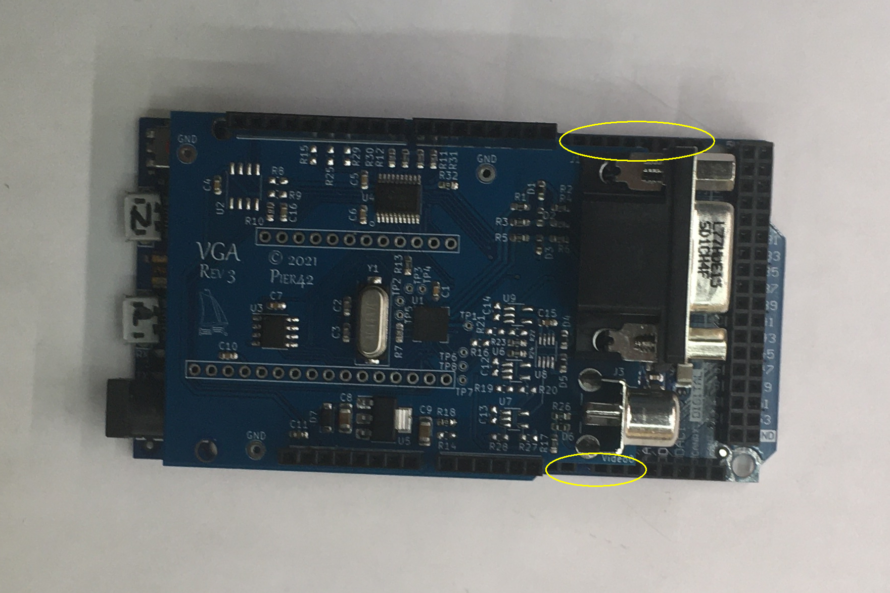
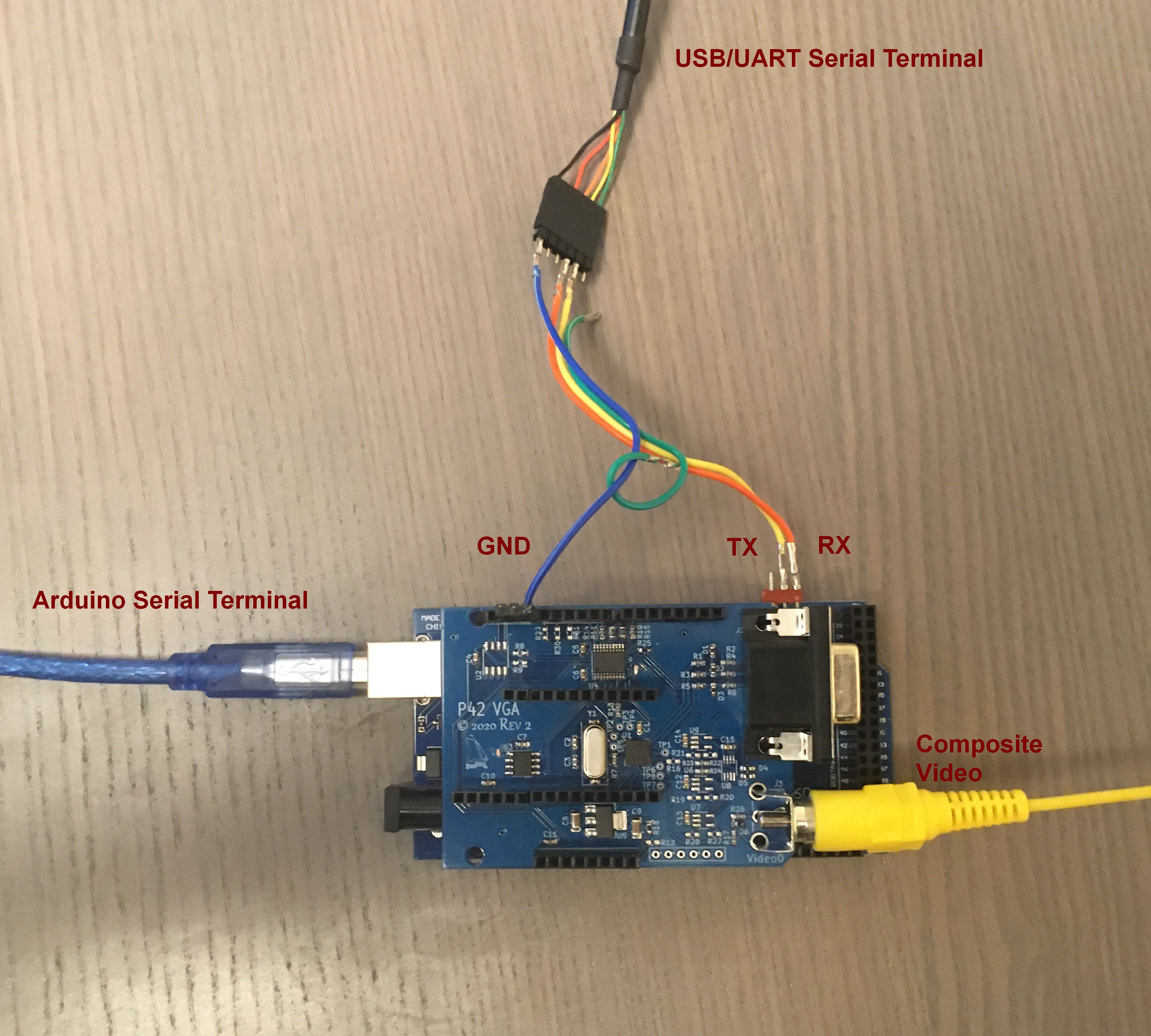
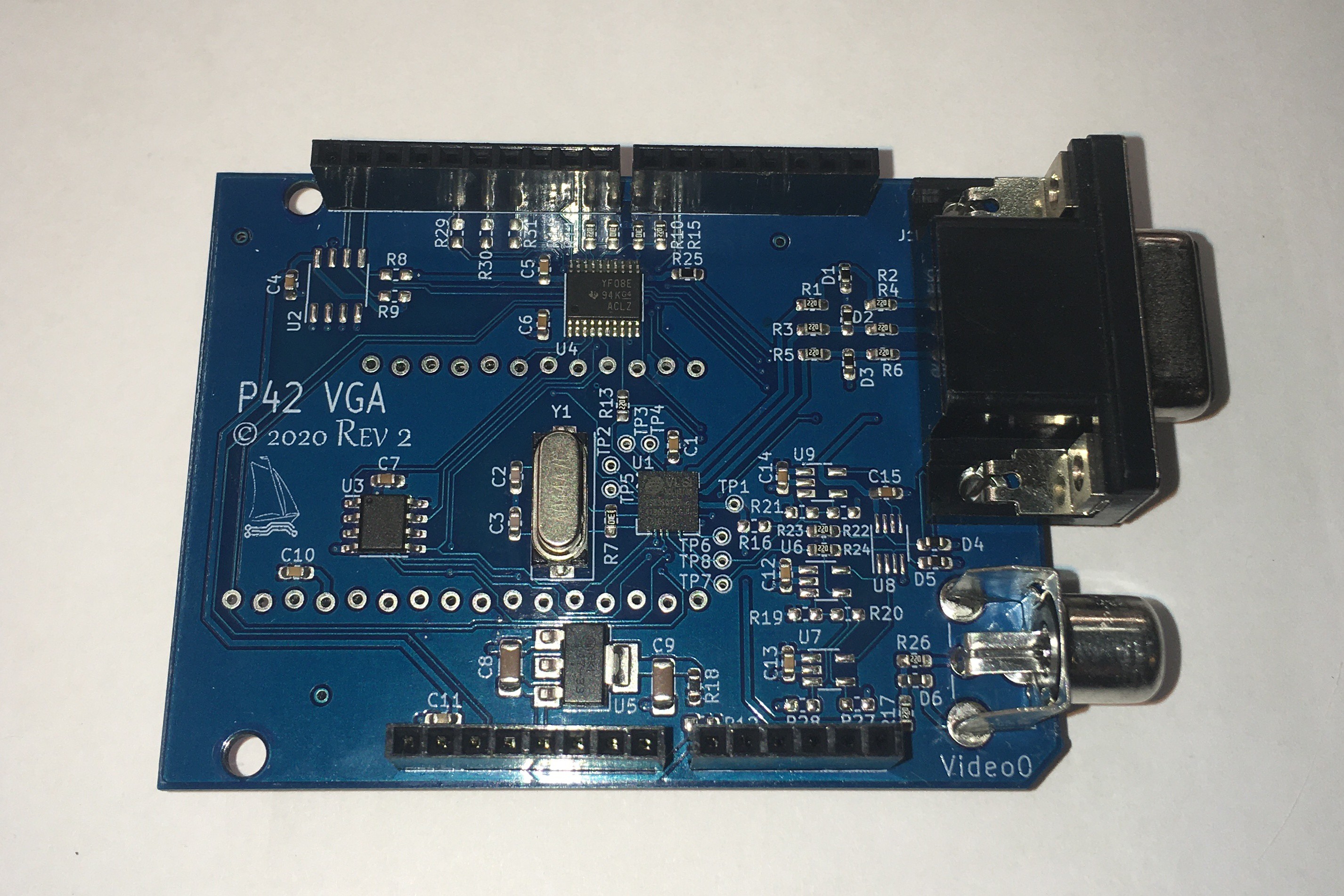
The VLSI VS23S040 is the successor of the trusted VS23S010 composite video chip with framebuffer. This Shield/Wing uses the VS23S040 to generate VGA signals or composite video.
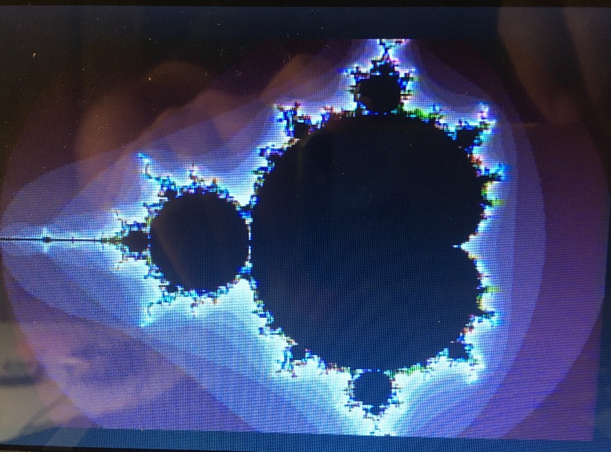
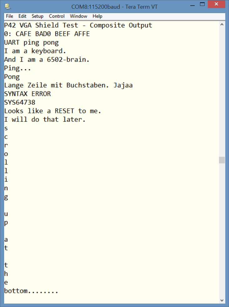
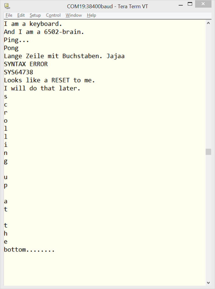
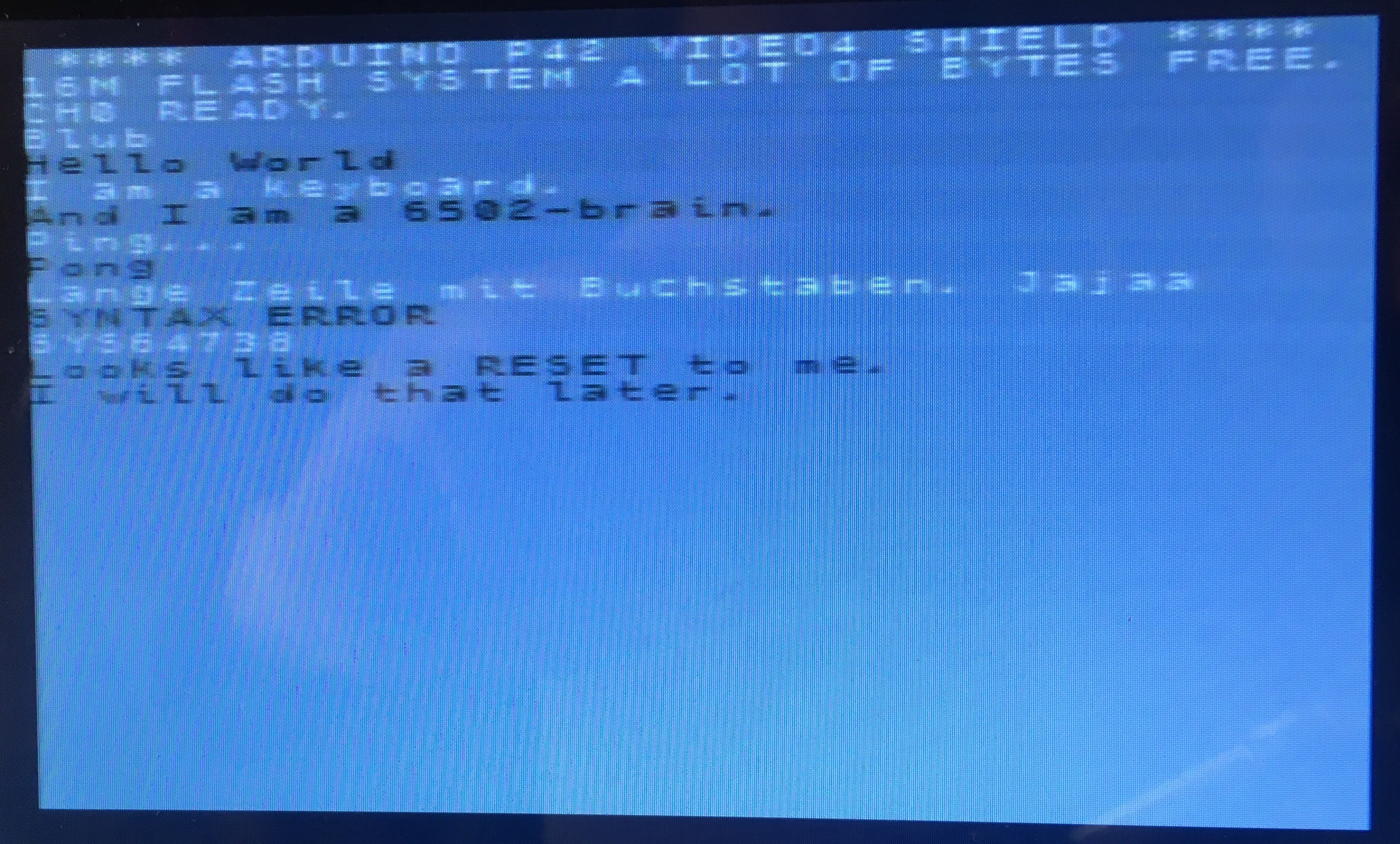
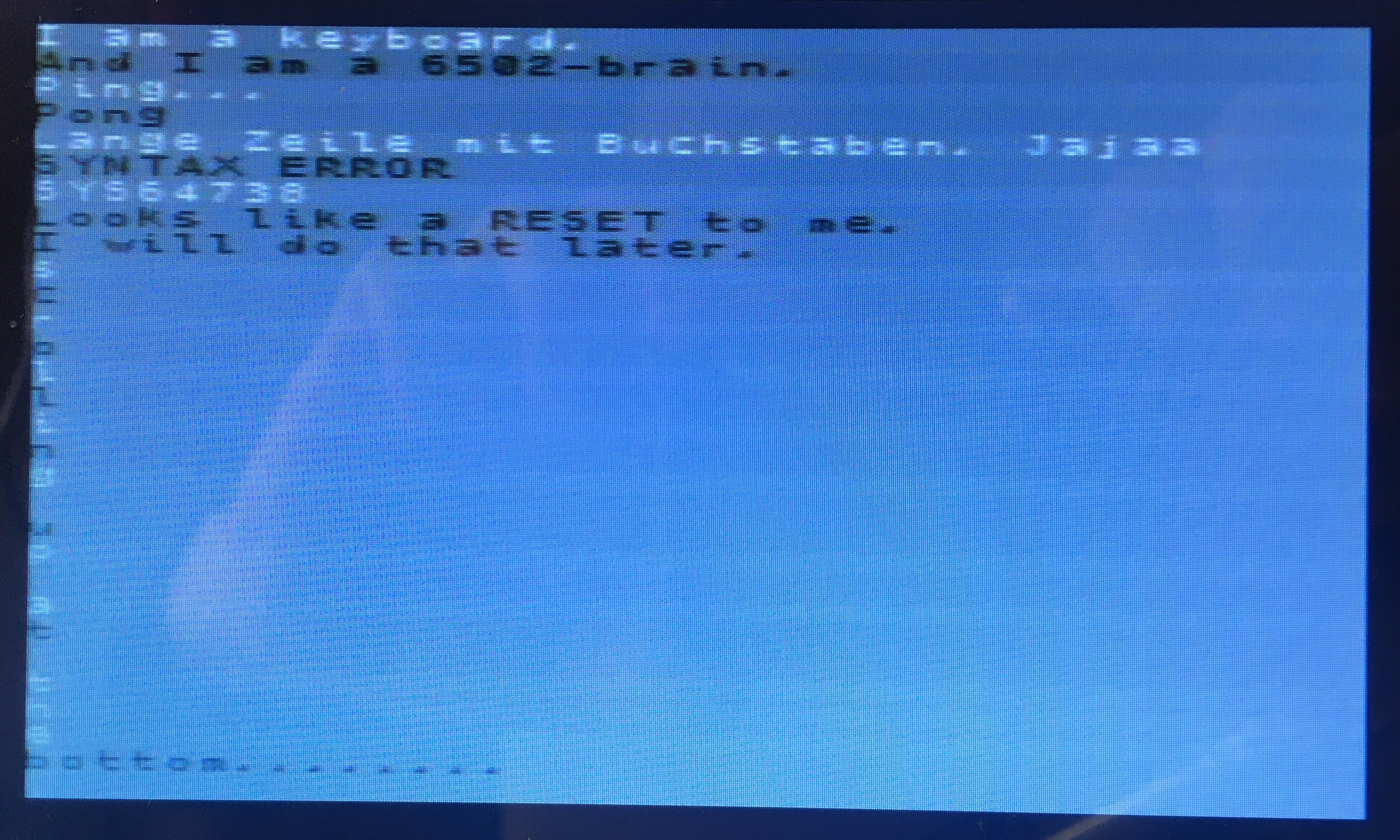
Currently it is running as 4x composite video output with resolutionS:
NTSC 320x200 in 256 colours and PAL 300x240 in 256 colours.
New resolutions in composite video mode:
NTSC 426x200 in 256 colours and PAL 500x240 in 256 colours.
I plan to get it running in the future as VGA with 640x480 resolution with 3bit per RGB to generate 512 colours.
VGA sync signal are running stable, next is the colour output. Software will be released when output is fully functional.


 Stephen Moody
 Peter Hizalev
 PK
PK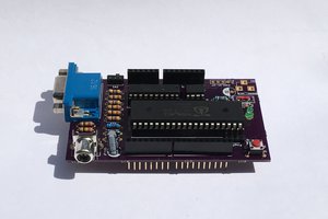
 Dylan Brophy
No more reply, 4 comments deep ;(
I think there was a comment from Panu in the VLSI forum about the S040 dies.
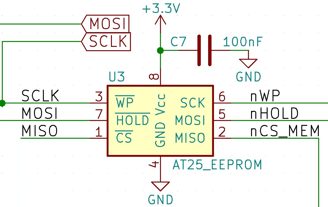
SPI works tricky, as everything else in the chip. There is a register to disable access to any of the 4 register/memory sets. So you can write all 4 or only selected ones at the same time, same as 4 identical chips connected to an external SPI bus. For read commands only one can be enabled to give a meaningful answer.