 kamalkedin123
Principle:
The temperature controlled system works, when the temperature is more than the surrounding the Op-Amp output flows across the circuit is high, which is passed to the motor fan for the cooling of an system and acts as a coolant component. Since we have connected the driver motor to the ground the output of L293D is high and the fans motor starts rotating resulting to the temperature decrease of the system. This types of temperature controlled systems are mainly used and implemented in automobile industry, water heaters, refrigerators, coolants etc. so lets make our temperature controlled system.
Components Required:
- L293D Motor Driver IC (1)
- LM358 Op-Amp (1)
- LM35 Temperature Sensor
- DC Fan 12V (1).
- 10k Ohm Resistor (1)
- 5k Ohm Potentiometer(1)
- Bread Board
- 12V Power Supply
- Connecting wires (as required)
Circuit Diagram

Procedure:
1. Place the LM35 Temperature Sensor on the bread board

2. Connect the one terminal of LM35 to the positive rail of the bread board and other terminal to the ground.

3. Now connect 10k Ohm resistor as show in the figure below with respect to the circuit diagram

4. Connect a 5k Ohm potentiometer with one of its terminal to the positive rail of the bread board and other terminal to the ground


5. Connect the wires to the potentiometer for connecting it to the LM358 Op-Amp

6. Now connect pin 2 of LM358 to the potentiometer

7. And pin 4 to the ground as show in the figure below

8. Connect pin 3 of LM358 to the temperature sensor

9. And connect the wire through pin 1 of LM358 to connect the IC chip motor driver

10.Now place the L293D motor driver on the bread board with its Pin 2 connected to the Pin 1 of LM358

11.Connected the Pins of motor driver as per the circuit diagram to the positive rail of the bread board

12. Now connect the respected Pins of motor driver to the negative rail or the ground of the bread board

13. Now extend the terminals of the power supply with the connecting wires as shown in the figure below

14. do the same for the ground terminal connection on the bread as per the circuit diagram with respect to the figure shown below

15. Now connect the 12V DC Motor Fan to the Pin 3 and Pin 6 of L293D motor driver.

16. Connect the 12V power supply as shown in the figure, positive terminal of the battery to the positive rail of the bread board and negative terminal to the ground.

17. Now take some heating element like soldering Iron closer to the LM35 temperature sensor.

our DC motor will starts rotating because of the temperature sensitiveness detects by the temperature sensor.
When we take our heating element away from the temperature sensor, the fan motor stops rotating

This is the basic principle and functioning of a temperature sensitive controlled system.
Thank You.
 brooksware2000
 mosaicmerc
 Jasper Sikken
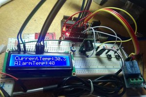
 icstation