0%
0%
VDC-II
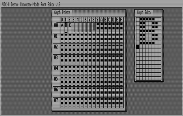
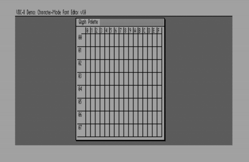
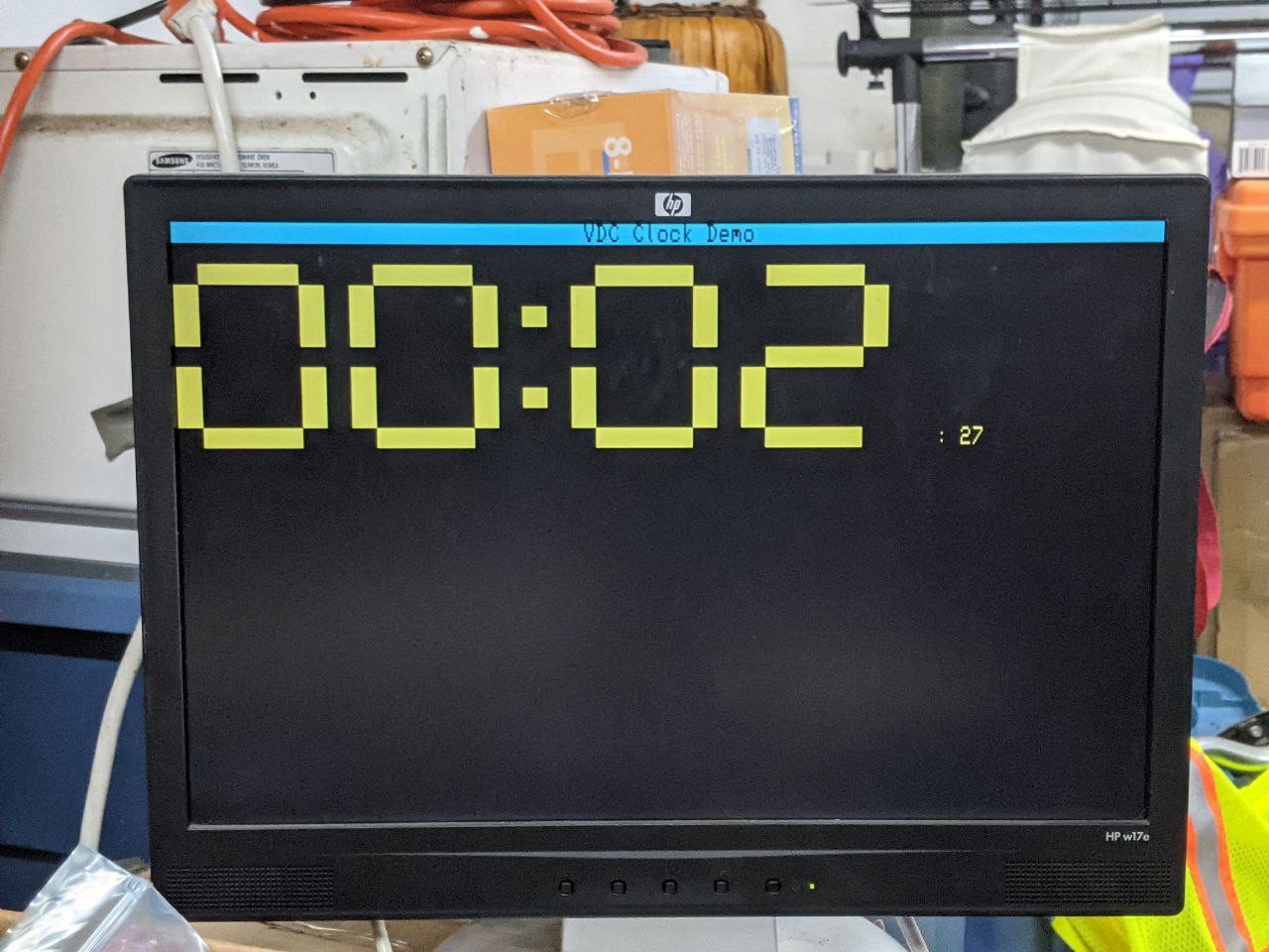
Commodore 8568-inspired (and mostly compatible) video core for driving VGA-type displays.
 Samuel A. Falvo II
Become a Hackaday.io member
Already have an account? Log in.
Just one more thing
To make the experience fit your profile, pick a username and tell us what interests you.
Pick an awesome username
hackaday.io/
Your profile's URL: hackaday.io/username. Max 25 alphanumeric characters.
Pick a few interests
Projects that share your interests
People that share your interests

 Carson Herrington
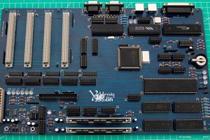
 Stephen Moody
 Jorj Bauer
Coming along nice, I'm eyeballing it thinking it would be a "known" display for playing in CP/M with for any progs that targeted 128s CP/M mode. Not that I'll have a full 128 for that, just some as yet undetermined z80 board. Thinking of growing it from Roy Searle's minimalist version.