Minimum hardware
The goal of this task is to try and test minimum hardware solutions that can match the requirements of the project.
Minimum hardware is at best the most difficult part to define. The reason for this is that the objective of this project was also to try and have a high speed response, normally not compatible with the "minimum hardware approach". It's also the most difficult part for me to define since it's just really not my area. Nevertheless, I'll have a crack at at it and learn something along the way. That's what projects are for after all! In the meantime, forgive my many errors as I got trough this quest and let me know if there are better ways to implement this task.
So, in order to implement the simplest decision tree that was modeled using the data from the MNIST database in this project, I'd need a minimum of 13 pixels. Minimum pixel sensors, at hand, light dependent resistors, or LDR for short. These are reasonably cheap, widely available and can act as intensity sensors, readily able to measure the intensity of each pixel and translate it onto a voltage with a voltage divider.
Once the signal is ready, that's when the project becomes interesting since I have two types of solutions at hand, a Digital and an Analog solution.
Going digital
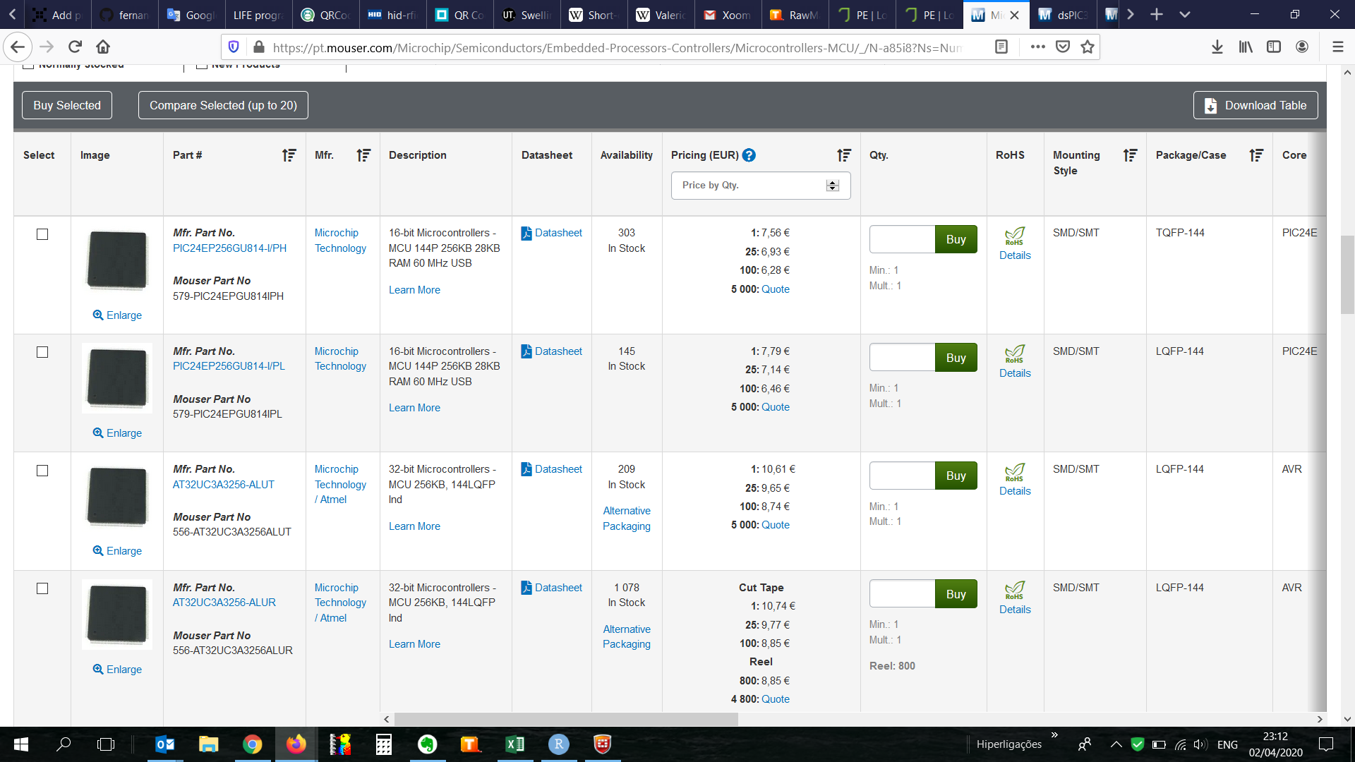
In order for the decision tree to be managed digitally, the information from the sensors would have to be received by an analog input and transformed onto a signal by an ADC. Now, there's quite a few micro controllers with 8 channels and then looking through the Mouser website I came across the PIC24 and PIC32 families with a whooping maximum of 122 IO, from which at most 32 IO cold be used as analog. Looking at the minimum model developed in the previous task, 32 analog inputs or pixels will not bring enough scale to the model, i.e. model scalability is hindered, and by limiting the model size, so is accuracy.
I know that digital signals can be multiplexed and then quite a few more IO signals could be accommodated but then we'd be adding layers to the system with time consuming operations. Bear with me, if possible, the goal is to have as simple a system as possible, even if that means capping the model to the available IOs.
Since this is not really my area of expertise and probably there are solutions out there with more than 32 analog inputs.
It does look like the most likely solution to a complex decision tree, and keeping with discrete component logic, the sensors would have to be multiplexed turned onto a digital signal in order to accommodate the large number of splits needed in the minimum 300-node decision tree model.
I'll call this the benchmark limit, to be upgraded once a new solution comes my way.
Going analog
Now, most of the information in this project is common knowledge, but for me most of it is eye-opening. For example, something as simple as turning a split in a decision tree onto a circuit was a mammoth task.
My first idea was to use transistors in a Schmitts trigger configuration. For those of you who know, it's obvious it'd never work since it has too much hysteresis and it just wouldn't switch if there were small differences in consecutive digits. So, first fail.
Second idea was to use transistors as Darlington pairs. My idea was to try and amplify the signal and create a split from "nested" pairs. This didn't work either since the voltage drop from consecutive pairs meant the after my second split, there was not enough voltage to do much at all. Second fail.
After shuffling trough some literature (ahem google), I came across the concept of voltage comparators. Yes, I know, for those of you who know... Well, for me it was an interesting trip down op-amp lane.
Well, the question is, can it beat an FPGA? That's a really hard thing to answer and I hope someone that knows what they're talking about can really help out here. Nevertheless, I'm going to go on a limb here and make some assumptions. For simplicity, the decision tree used for comparison will be one of the simple models from the minimum sensor log. Sensor speed will be assumed the same for both solutions.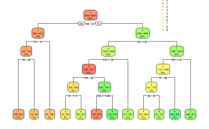
Voltage comparator:
- The tree is 5 levels deep.
- The fastest comparators I could find had a minimum response time of 7 ns.
- Maximum response time, for the digits with 5 levels would be in the order of 35 ns.
High end FPGA:
- A fast ADC, like the MAX158BEAI+ has a sampling rate of 400kS/s with 8 channels, hence, we'd need two ADCs. Since the time is per channel, we could just brute-force it by using instead 11 single-channel ADCs. That caps the time to 2500 ns.
- The clock speed on a Stratix IV FPGA, claimed the world fastest, is 600 MHz, i.e. a cycle time, if everything runs on the same loop, of 1.6 ns. It doesn't really make a difference if we use one that is even faster, it's going to have to wait for the ADCs.
Conclusion
So, final solution, voltage comparators, LDRs, some resistors and LEDs of course to show which digit was detected. Can it get any simpler than that?
And the million dollar question, can a circuit built with voltage comparators beat an FPGA? In this case, and if my analysis is not too flawed, I'd say it beats the crap out of it. And it's a little bit cheaper as well.
Final step, prototyping.
Discussions
Become a Hackaday.io Member
Create an account to leave a comment. Already have an account? Log In.