The goal of this task is to design a PCB that will allow a trained neural network to be used to detect MNIST numbers from an image.
Sensor array and signal selection
During the analysis of the results reported in the previous log, I realised that actually jumping from a 16-pixel sensor matrix to a 49-pixel sensor matrix had two significant effects. The first one was in the design of the sensor array. The second one and even more significant was on the memristor. Considering my limited experience in PCB design, and looking at simulations of the memristor in action, I decided to stick to 4 x 4 matrix using the intensity level from the sensors instead of the binary response. Also because the 7x7 matrix using the model with a binary signal did not perform that well and it had a very significant cost in complexity.
Assuming like I did for the previous model an average of 1.5 components per node for the memristor, and using 49 inputs and 10 outputs, I'd have a whooping 450 components to mount (that'd be for every input, 10 weights and a bias, multiplied by the number of outputs). Anyway, my initial 1.5 component per node was a little bit off as we'll see later.
The attached simulation can be run here and shows that the neural network is quite robust and small changes in some of the sensors do not make a significant difference in the result. Nevertheless, we'll need to test this in real life.
The simulation actually helped me to see a significant issue with the design that I had not predicted. This was quickly solved with a bit of learning about passive components. Shocking as it was for me, I didn't know electricity could flow backwards.
Memristor design
The initial memristor design needed a bit of math to adjust the negative weights. The positive weights were calculated simply by multiplying the input voltage by the conductance of the resistor, the result being a current.
For the negative weights, I needed to subtract the current, and this was achieved by using an npn transistor that would conduct the current in the base multiplied by beta (I didn't even know this number existed, learning as we go long). So, all things considered, I found out that beta was not constant with the input current.
If anyone knows of a type of transistor that has a beta that has a small variation with current, please send me a comment. I'd really appreciate any help on this.
I tested the impact of a variation in beta in the simulation and found that this was also not very significant on the result of the neural network. Then again, we'll have to test this in real life.
So, my problem appeared when I put an LED at the back of the digit line. In order to see whether it's one digit or the other, I chose to add an LED with a resistor. The problem was that the current in some conditions, chose to flow backwards instead of forward in some conditions. Since the signal is a current, I could not afford losing current to other part of the circuits. This was quickly solved with a diode in line with the input resistor as can be seen in the video below.
This is an incredibly basic concept but up until this time I had never actually needed a diode, nor I knew very well how they worked. That last bit still holds today.
Instead of having nodes with a 1.5 average component count, I had now two. Initially the nodes with positive bias had a resistor and the ones with negative bias a resistor and a transistor. In big numbers average 1.5. Now I had a diode and a resistor for the positive bias and a resistor and a transistor for the negative bias. Total count was now 16 inputs , 1 weight per input plus a bias for each multiplied by 10 outputs, 2 components per node. Theoretical part count 340. The actual value came a little bit higher due to connectors and LEDs, but close to the mark.
So, with my small simulation out of the way, I proceeded with a bigger simulation, with all 16-inputs weights punched into the circuit plus the bias. I then adjusted all the voltage values for a number which I knew that should light up the led and lo and behold, it worked!
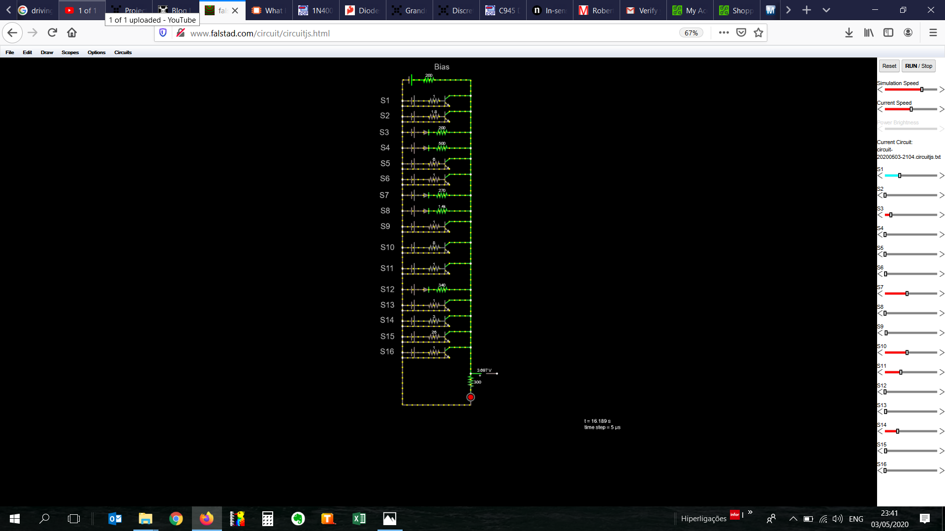
What a freaking Eureka moment!
I had a working (virtual) circuit of a neural network. This was huge. Being able to translate a neural network model onto a functional circuit was really a very happy moment.
There were two important takeaways from this picture. The sliders on the right allow me to adjust the voltage of the input sensors. I then managed to see that adjusting the values of some of the sensors one way or the other, did not affect the result too much. The system is robust in a way that all 16 inputs have a say on what the number is, whereas in the decision tree, one sensor had the power to upend the whole thing.
So I had a working circuit, it was time to make a pcb.
Designing a PCB
I never designed a PCB, but I thought I'd have a crack at it and started with the sensor matrix.
I read over an again people swearing by Eagle, then Kicad, then setting the comment section on fire, I decided in no particular order to try Eagle first. After a few tutorials and some messing around with schematics, I found myself severely limited with the free version of this software and moved on to Kicad. Honestly, it was not as painful as I was expecting the learning curve to be. I followed the video series from Ashley Mills and found myself making PCBs in no time.
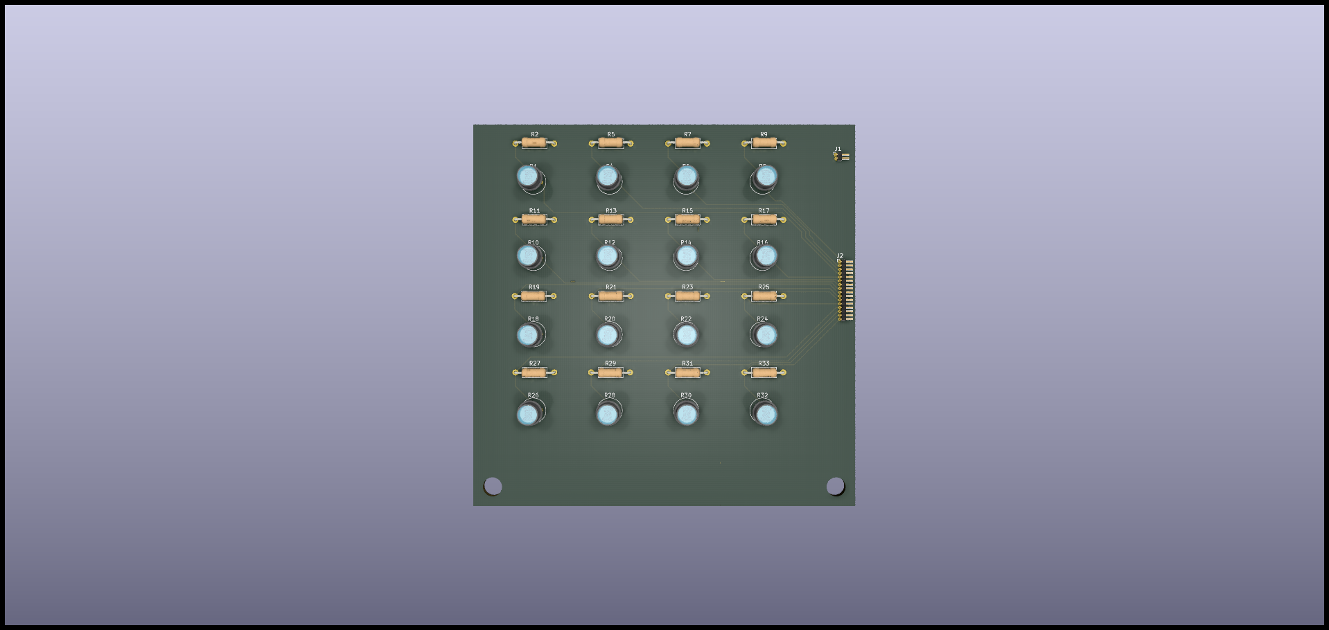
The result was a square matrix of LDRs with their respective resistors to have the signal out already in the form of a divided voltage. The schematics and pcb file are attached here and here.
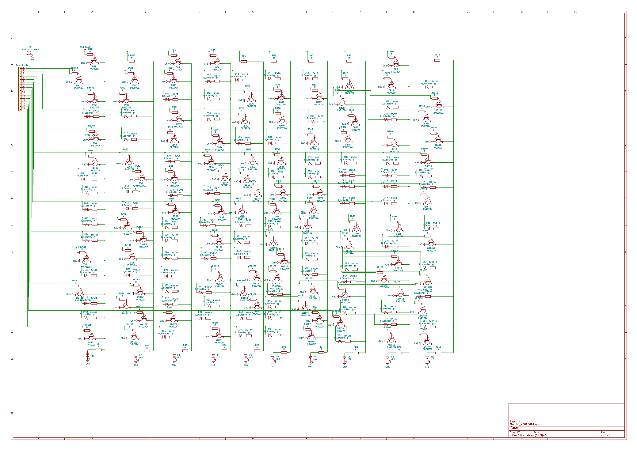
Since things were coming along nicely, I decided to have a go at designing a digit line for the memristor. After finishing the first line, I realised that the output didn't mean anything since the result is just the brightness of an LED. In order to tell apart whether it's a 1 or not, I'd have to have another LED saying which other number it could also be. So I decided to draw another digit line. In the end, I drew all 10 and realised the monstrosity this thing had become. The schematic fitted comfortably on an A2 piece of paper. This was bigger than I had bargained for. By far.
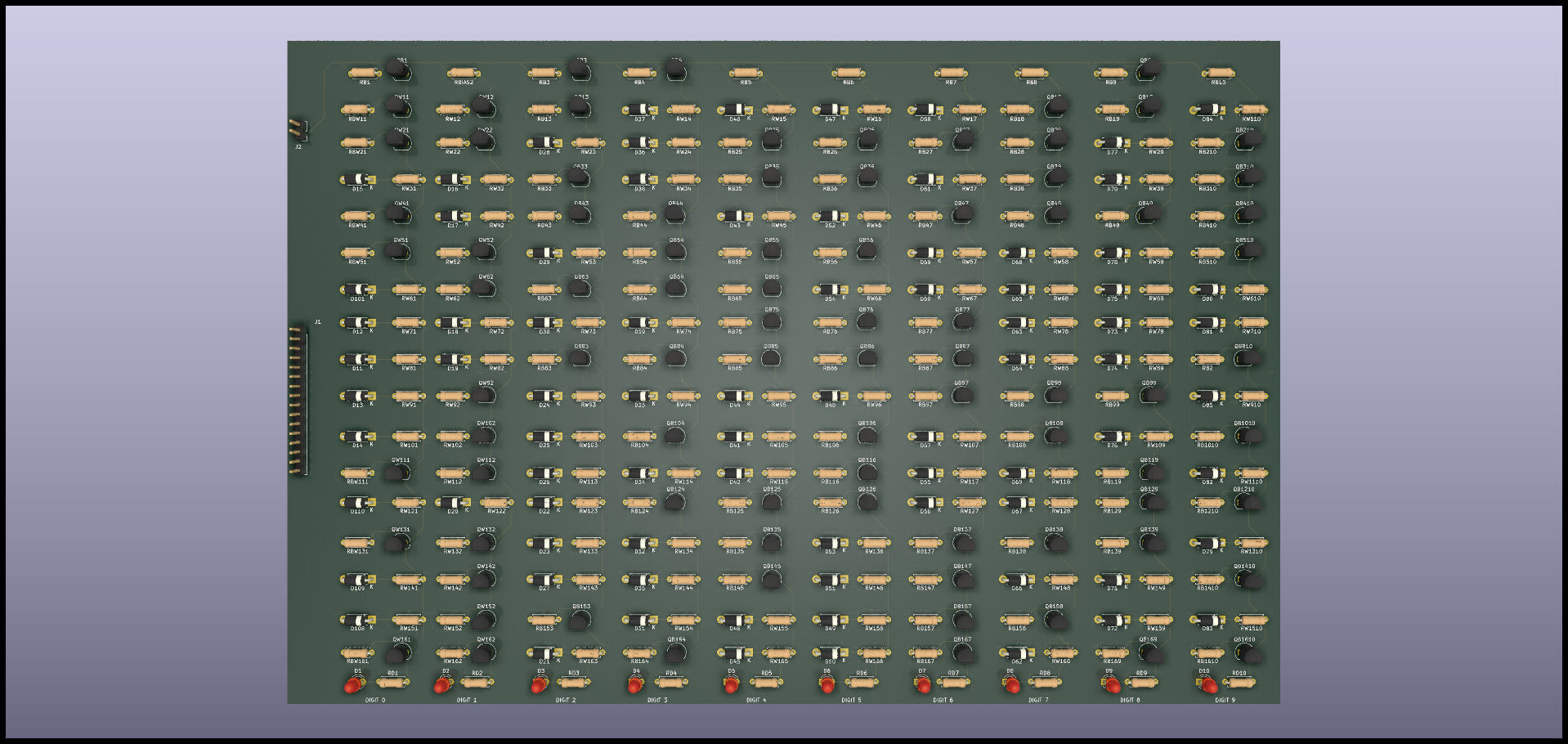
Eventually the schematic was placed on a board and could be fit onto an A4 size PCB. I'm pretty sure it can be made smaller, but then I'm also not very good at soldering so I tried to leave some space to work more comfortably. And I'm not sure I did a good job at that.
The resulting PCB looks like something I would have expected to see if I opened a machine some 30 years ago. The packed project can be found here.
Conclusion
It's a really exciting moment for the project and one I didn't think would come one day. The project was really focused on decision trees, not neural networks in mind. Nevertheless, things evolved naturally.
I did have a go at making a decision tree PCB, but then I dropped it very quickly to make the neural network.
It has been overall an incredibly fulfilling experience, and I have learnt a lot long the way.
Now the question is: Will it work? There's only one way to find out.
Disclaimer: I've never designed a PCB before and also don't have an EE background so use the information here contained with caution.
Discussions
Become a Hackaday.io Member
Create an account to leave a comment. Already have an account? Log In.