Reverse Engineering Grant ASHP Remote Protocol
Reverse engineering the protocol used by our Grant ASHP remote.
Reverse engineering the protocol used by our Grant ASHP remote.
To make the experience fit your profile, pick a username and tell us what interests you.
We found and based on your interests.
Gerber_PCB_2020-10-04_12-14-26_2020-10-04_15-40-00.zipGerbers for PCBZip Archive - 139.99 kB - 10/24/2020 at 11:52 |
|
|
PickAndPlace_PCB_2020-10-04_12-14-26_2020-10-04_15-40-10.csvPick and Place for PCB (not particular useful for this design)Comma-Separated Values - 7.24 kB - 10/24/2020 at 11:52 |
|
|
BOM_Heatpump_2020-10-04_15-38-58.csvBOM for PCBComma-Separated Values - 3.24 kB - 10/24/2020 at 11:52 |
|
|
digital.srSigrok output from the T6B70BFGsr - 1.01 MB - 03/27/2020 at 22:28 |
|
|
analogue.srSigrok output from the remote control connections (the twin core)sr - 1.55 MB - 03/27/2020 at 22:27 |
|
It's been a while...
Since the last post, I went ahead and had my gadget control the CH and DHW demands, replacing the room thermostat. This consisted of using the 'spare' optocouplers to drive a pair of 5V relays, and also using some DS18B20's to measure room temperature, and the temperature on the CH buffer and DHW cylinder. There were some integration issues (it seems that switching the relays sometimes upset the DS18B20s) but the system worked well. Well enough that I stopped fiddling with it, which is quite some achievement :-)
However, "working well" isn't "working perfectly". My main 'issue' was that I was only turning the heatpump 'on' and 'off' in response to room temperature. If it was cold out, the weather compensation would ramp the compressor right up, even if the room temperature was only a little under the set point, resulting in short cycle times and a noticeable room temp fluctuation. Alternatively, if I dialled back the flow temperatures in the weather compensation settings, it would trickle for hours slllooowwwwly warming the building up. I needed some control over flow temperatures.
Trying to do this by 'pressing' the buttons was not feasible. Requesting the basic 'user' data was tedious enough, but to set 'installer' variables required one additional button, and many button presses (too each to 'miss' a press and get out of sync). Time to try talking directly to the UART again...
My first attempt was to cut the connection between the MCU in the remote and the transceiver chip, and insert a microcontroller under my own control and essentially perform a MITM attack. I would need to forward bytes between the MCU and heat pump as quickly as possible, and then 'insert' my own messages in the gaps between transmissions. It's only 1200baud, how hard could it be...
This needed a micro with at least two UARTs (software UARTs should have worked, but the low speed meant long delays and slow interrupts. A third hardware UART would be handy as a 'console' connection over USB so I could see what was flowing back and forth). An Arduino Mega would have done the job, and is 5V, but it rather large. An ESP32 is faster, has three hardware UARTs (with user-definable pins), and also has wifi built in. Ideal, although the 3.3V logic needed a logic level converter - not a problem, still got a pack from last time...
One (of many) quirk is that anything transmitting to the transceiver chip would immediately receive an echo due to the way it works. Handy in one sense (easy to check for collisions or other corruption as the message is being sent), but also means I have to keep the MCU happy by echoing its transmitted bytes back to it. I quickly found that just Serial.write(Serial.read()); wasn't quick enough. Connecting TX to RX should have solved that, but introduced other problems (have to clear the RX buffer after transmitting, without trampling genuine RXs, two TXs and two RX lines connected together causes pull up problems)... eventually it became clear that I wasn't going to be able to get this working quickly (also considering that while I was fiddling, the heating to the house was off).
Attempt two restored the connection between the MCU and transceiver across a couple of resistors, with the ESP32 now connected strategically each side of the 'RX' resistor. The plan was I could 'blind' the MCU by pulling it's RX line high while I was transmitting (preventing it seeing bytes that it didn't send), while still being able to read the RX line before the resistor...
It (sort of) worked! I also had to perform another dirty hack to move the Serial TX pin around (the TX pin was of course holding the TX line high, preventing the MCU from talking to the heat pump), and I was still not entirely satisfying the MCU (the remote was still erroring out, but was either unable or not trying to disable the heatpump as before) but I could send messages and receive responses! I had previously decoded much of the serial...
Read more »With the PCB manufactured and delivered, components were quickly soldered in. To program the ESP-12F, the TX and RX jumpers are removed, and a jumper moved from 'run' to 'prog'. I used a handy nodeMCU (plugged into to 3v3, Ground, RX and TX, and reset) as a usb interface and flashed the ESP-12F using the Arduino IDE.
Then wired it up to the remote...
It worked! But two (related) issues.
The solution was to cut the two tracks, and a simple couple of wires added so that GPIO1 was now connected to the DS18B20 (thus held high) and GPIO16 now drives the solid state relay (and is now only an output). These changes have been made on the PCB designs, but no need for new ones to be manufactured for my purposes.
The system now works perfectly! In the future, I intend to have the module also drive CH and DHW demands, replacing the existing programmer/thermostat (This thermostat implements TPI, which switches the CH demand on and off in order to eliminate room temp hysteresis. Fine for a gas or oil boiler, but almost exactly what you don't want on a heat pump, where long, low temperature, runs are more efficient. And yes, it was installed as part of the heat pump installation...)
PCB design files can be found on easyEDA and also github, where the firmware for the esp can also be found.
So now I have a working system that monitors the heat pump performance and status. One or two issues though...
The clicking from the relays is annoying. And they'll wear out eventually.
The relay board is bulky and untidy, so it's currently out in the open.
Occasionally the esp crashes. This appears to be related to switching a relay at the same time as the heat pump stops, so probably power/noise related. The esp starts again, but there is currently a fixed delay before it starts 'pressing buttons' (it assumes the system has just booted and is initialising) so misses some data sometimes.
Resolving the third issue has two parts - first, the software is changed so now it doesn't assume a full boot (it tries to request some data from the ASHP - if the esp has crashed and rebooted, the remote will still be on the request screen. If successful, it's a esp crash/reboot, and it'll continue where it left off. If that fails, it knows this is a whole system boot, and it waits and starts from the beginning). Secondly, improving the power filtering and noise immunity of the system would be useful. (There were a lot of wires just flopping around... Removing the relays wouldn't hurt either)
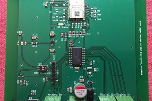
So I designed a PCB. This used some solid state relays and an esp-12f.
(note that this PCB does have an error, corrected in the GitHub gerbers)
The PCB has solid state relays for each button, plus two spare (these could press other buttons, to allow changing ASHP settings, or replace the thermostat/timer for CH and DHW demands, in the future) It could be made more compact (is used large resistor and capacitor footprints, these could be smaller, or even SMD) but fits nicely behind the remote as-is.
Now, software...
I have an OpenEnergyMonitor EmonPi set up here, which monitors my electricity use. OpenEnergyMonitor does have a project to monitor heat pump performance, but relies on its own sensors that need installing within the system, including an expensive heat flow meter. My heat pump includes all of these sensors (apart from the heat flow meter), and can report their readings through the remote, so it seemed sensible to try to get the data from the system instead of installing a load of duplicate sensors.
From a cold start, to start reading data, you must wait for the ASHP and remote to initialise (~30secs), then once the system reaches standby/operation, hold the 'back' button on the remote for ~3 seconds. This takes the remote to a 'parameter read' screen. It is then possible to select the parameter to be read by pressing the 'up' and 'down' buttons, and request the data with the 'tick' button. The ASHP will then send the data to the remote, which displays the number on screen. It is possible to request data from parameters 00 to 99, but the vast majority of these are empty. The manual lists parameters 00 to 09, and there are a few additional undocumented ones higher up, but these have not been identified. 00 to 09 contain all the interesting ones, anyway.
Once remote sends its first request and receives the data, it can then select and send the next request, cycling through 00 to 09, and then back down again. Iterating through this will receive all the useful data.
Additionally, the ASHP periodically sends other data - this includes date/time, status (power, fan, pump, compressor, DHW and CH demands), and outside air temperature. These can not be requested, so we must listen for these. (Actually, we can, and do, request outside air temp, but the response is to the nearest degree celcius. The oat sent periodically is to the nearest half degree, so this is 'better'. We ignore the requested OAT.)
We also read a DS18B20, which is stuffed into a thermostat pocket on the hot water cylinder. This is read every 5 seconds (this is overkill, but hey ho)
As the esp receives the data, it sends it to the EmonPi using it's api. This is relatively simple.
As the remote is now less useful (when the esp is cycling through, requesting data, the standard display is unavailable) we also run a http server on the esp, showing a 'pretty' status display with pumps, fan, compressor status and temperatures.
A short delay since the last post...
I went ahead and disconnected the buzzer from the remote, and wired hookups to the switches I need (Up, Down, Tick and Back)
Measuring the voltages while pressing buttons indicated that the inputs were active high, but weren't being pulled up to 5v like the rest of the board. Voltages read to ~3v. Excellent news, I thought, I can drive these direct from the esp!
Needless to say, this didn't work. Each 'button press' was registered by the remote as multiple buttons being pressed. Further investigation revealed that the buttons were being multiplexed by switching their commons at ~250Hz, with three 'groups' of buttons sharing three 'commons'. Each of the commons is switched at ~250Hz with approx 30% duty cycle, phase shifted so as not to overlap. The μc in the remote can then work out which button is pressed.
My first thought was to have the esp listen to the clocked common, and bring the switch lines high and low in time, but I couldn't get this to work reliably (perhaps easier with a 'duino rather than the non-real-time esp). Next, I tried using AND gates across the switches, but this was even worse. I suspect this was an implementation problem.
Next, I used a 4-way relay board across the switches. This worked! But the clicking was frustrating... and the resulting mess was bulky. It did, however, provide working hardware to develop some software on.
So, I've made some more discoveries.
The first, and most positive, is that the second and third-to-last bytes in each word are definitely a CRC. I found an implementation of the 16bit CRC-CCITT algorythm which produces matching results to the packets I've recorded. This is good - not only can I more robustly check the received data, but I can write my own packets to transmit.
Next, I tapped into the tx and rx line on the remote between the T6B70BFG and its uc. First, I concentrated on decoding what the T6B70 was receiving (due to the transmission, this also included transmissions from the remote). An esp8266, logic level shifter, and a bit of code saw success (a 5v arduino would also work nicely, of course). 1200 baud is very slow, but allowed receiving characters one at a time, working out the expected message length, message type and received data, and also calculating the crc and checksum and confirming the packet was good.
So now I had access to any data sent by or to the remote. This only included day/time, outside temperature, and power/pump/fan/compressor status (on or off). Useful, but not everything I wanted. To get to the other data, the remote has to request it. I tried sending a request packet from my esp, including the 18ms delay between each byte, and... nothing.
Using my logic analyser, I could confirm that 'my' packet matched the request from the remote exactly, but didn't also appear on the RX line! The esp wasn't pulling the TX line to zero hard enough to overcome the pullup from the remote's uc. Cutting the trace and inserting a 270ohm resistor between uc and esp pins (so the uc had to drive through the resistor, but the esp was driving the T6B70 directly) was more successful, and the esp could now pull the line much closer to 0V (and was being seen on the RX line too), but the remote could still send packets too.
Unfortunately, although I could now transmit the request packets, I ran into the next problem. Any time I tried to transmit 'my' packet, pretending to be the remote, the remote would notice and error out, producing a series of loud beeps. In addition, it would immediately send another packet to the ASHP (presumably announcing its error status) and the ASHP would not send the requested data.
I attempted pretending to be a second remote by setting the 'send' address to 0x02. This didn't upset the remote, and got to the ASHP, but instead of the data I wanted, all I got back was a strange new packet, which I assume was something like 'unauthorised'...
I did try, using my logic analyser, listening the the rx and tx lines as I powered up the system, in the hope that I'd find an 'authentication' or setup conversation. I think I did, but as it consisted of over 200 bytes, the likelyhood of being able to understand enough of it to register as a second remote is unlikely, and even if possible, would probably require crafting correct responses to the ASHP's periodic packets.
This was frustrating. If I manually requested each bit of data using the remote, my code would quite happily read the responses and could pick out the data from each packet. I had hope to keep my work on the remote minimally invasive, but I think if I want to get this data, I will need to 'fake' button presses to get the remote to request the data itself, and just listen to the RX line. This will have the side effects of a beep with each button press (the buzzer can of course be removed, I'll just lose audio indication of errors etc. Perhaps I can hold it silent somehow while I'm 'pressing' buttons), and the remote displaying each bit of data instead of the nicer time/day/status screen. However, as it has a door that shuts, and as I've already built a html5 replacement display...
So, more captures, and some decoding later...
When the system is sat idle, there is a periodic 'conversation' that takes place between the ASHP and the remote, starting each ~5 secs by the ASHP sending a packet, which is acknowledged by the remote, followed by some data from the remote, acknowledged by the ASHP:
-> 07 00 01 08 00 00 EF
<- 05 01 00 09 F0
<- 0E 01 00 97 08 0E 10 05 01 00 32 7B FE 82
-> 05 00 04 08 EE

-> 07 00 01 08 00 00 EF
<- 05 01 00 09 F0
<- 12 01 00 A1 00 16 00 00 00 00 00 00 00 00 00 33 26 DC
-> 05 00 04 08 EE

-> 07 00 01 08 00 00 EF
<- 05 01 00 09 F0
<- 0B 01 00 A3 A4 00 00 00 A4 47 C1
-> 05 00 04 08 EE

-> 07 00 01 08 00 00 EF
<- 05 01 00 09 F0
-> 05 00 04 08 EE
Also, on the stroke (or shortly after, if there is an ongoing transmission) of each minute, the remote sends:
0E 01 00 97 20 09 00 06 01 00 32 D1 62 C4
Other messages are also sent, but only on status changes - only the above are sent periodically.
There are several 'types' of packet.
The first byte is always the packet length (total, in bytes)
The second byte is either the sending station ID, or receiving, with the third byte (usually) the other. Packets from the remote are always 01 00, and from the heatpump 00 01 (apart from the 05 00 04 08 EE acknowledgement packet).
The 4th byte is perhaps the packet 'type'.
The last byte is a sum compliment checksum.
I have observed the following 'type' bytes:
0x08
This is seen as part of either 07 00 01 08 00 00 EF packet (requesting data from the remote?) or 05 00 04 08 EE (acknowledgement?) from the ASHP. Nothing interesting.
0x09
Only ever appears as a response (05 01 00 09 F0) from the remote to 07 00 01 08 00 00 EF from the ASHP. Again, nothing interesting here.
0x97
This one contains some data.
The remote sends day/time and stand-by/on data to the ASHP, and the ASHP sends the demand data.
0x98
This is sent by the ASHP back to the remote as an acknowledgement, and contains the same data.
0x99
Request from the remote for specific data from the ASHP.
Once this is sent, the ASHP will respond with 0x9A and 0x9C packets until the remote sends another request (I still need to find what it sends to stop requesting at all...)
0x9A
Data from the ASHP, usually in response to 0x99 packets, but also sent semi-periodically during DHW and CH demands.
0x9C
Data from the ASHP, appears to be sent occasionally and also in response to requests - perhaps just sends when a parameter updates.
0xA1
Sent by the remote periodically in response to the ASHP's 07 00 01 08 00 00 EF. Unknown, but must contain some data as some bytes change. (6th, 8th, 9th at least)
0xA3
Also sent by the remote periodically...
Read more »I made a number of captures today with the system in different states, hoping to identify messages.
I had assumed that the remote would request particular data, and that the heat pump would reply. This, however, appears not to be the case.
Much of the time, the heatpump sends:
07 00 01 08 00 00 EF
And the remote acknowledges:
05 01 00 09 F0
and then immediately sends one of:
0E 01 00 97 08 0E 10 05 01 00 32 7B FE 82
12 01 00 A1 00 16 00 00 00 00 00 00 00 00 00 33 26 DC
0B 01 00 A3 A4 00 00 00 A4 47 C1
(with small changes in places)
which is acknowledged by the heatpump with:
05 00 04 08 EE
(the above were collected while the pump was on standby, with no DHW or CH demand, and an outdoor air temp of 9.5 Celsius)
The first byte of each packet is the packet length in number of bytes.
The second appears to be an address (of the transmitting or receiving unit?)
The last byte is the checksum - sum complement.
Now for the rest...
For now, I'll focus on the digital readings I took, as they're easier to play with...
The above file is a ~30sec capture of the TX and RX (from the remote's point of view) pins on the T6B70BFG. As this is kind of a one-wire interface, everything transmitted is simultaneously received... The datasheet for the T6B70BFG mentions that the device will have to ignore its own transmissions.
It appears to decode as UART at 1200baud, 8N1 (although with large gaps between bytes)
I think I can see an ack packet, but this will take some time to decode, as the data potentially includes many variables. However, RX'd packets are of differing lengths, so the ASHP is unlikely to be sending everything all the time - more likely is that the remote requests certain data, and the ASHP responds accordingly.
It is probably possible to work out TX packets reasonably easily, as I can control what the remote asks for, and perhaps then either match up RX packets with displayed data, or send my own data to the remote.
The remote control is connected to the external unit, from which it receives power and data, by twin core cable. It can display the following data:
Not too bad! (but more variables to decode...)
DC voltage on the cable is ~12V, and the manual indicates that there is no specific polarity required for the remote.
Internally, the remote includes an R8C/L3AC MCU (which has many IO ports, A/D and D/A converters, and an LCD driver), a T6B70BFG (Toshiba, communications IC), a 5V regulator, and a full bridge rectifier IC.
The T6B70BFG reads/imposes a 250kHz 'sine-ish' wave over the DC supply:
Sigrok Analogue 'input' to the T6B70BFG
Sigrok digital 'output' from the T6B70BFG
Having my circuit read the analogue side would be less invasive, but may be more difficult.
Create an account to leave a comment. Already have an account? Log In.
Become a member to follow this project and never miss any updates

 David
David
 John
John
 markwarren.ee