 Ivan Stepaniuk
The stowaway microcontroller is also able to fool the thermostat into changing its set point to any temperature, by faking the encoder sequences as if the knob was being rotated.
The updates are received with Node-RED which serves as glue to tell Home-Assistant that the set point has changed. It also integrates with Alexa and keeps all three things in sync.
Honeywell nowadays sells a WiFi enabled thermostat very similar to this decade-old one, but:
- This one works when the cloud doesn't.
- I rent this place so I want this hack to be reversible.
- The smart version is quite expensive.
- ... What's the fun of that???
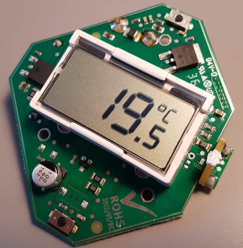
The original hardware:
The original thermostat is quite clever. It does not use batteries or dedicated power lines, it uses a charge pump to "steal" 5 volts from the boiler's normal open-contact connection. It does repeatedly this for only a few milliseconds at a time, but enough to power the thermostat, CPU and LCD, and never draining enough current for the boiler to detect a closed contact (or to detect it open when it's operating). It stores the stolen angry pixies in a 5.5 volt .25 F supercapacitor. Very clever!
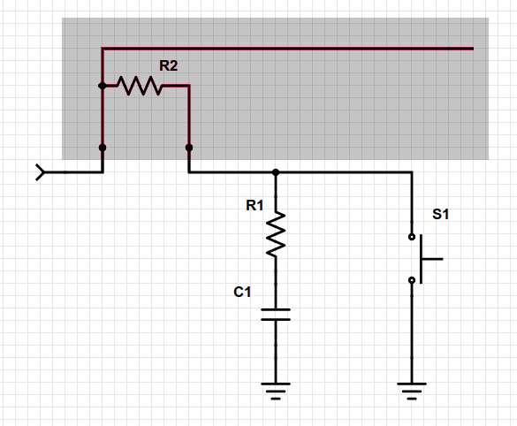
This is the original input configuration for each of switches that form the quadrature encoder:
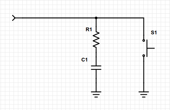
Note the absence of an external pull-up resistor, not that that's very uncommon these days in consumer electronics but certainly helps not to have these in this very low power device.
Both switches you see top and bottom of the PCB are actuated by levers which are pushed or released by this outer plastic ring:
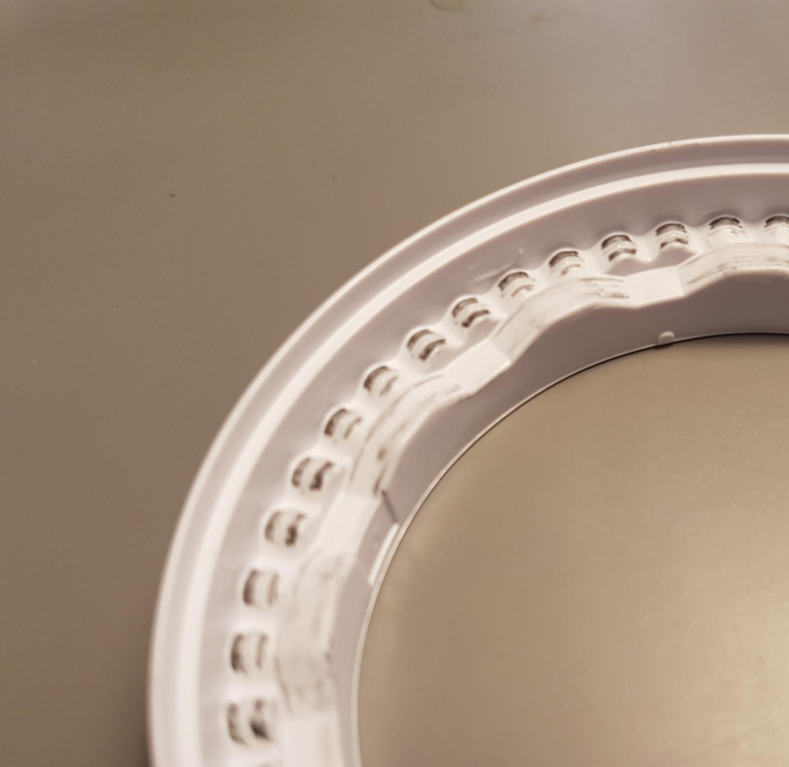
The outermost race is just detents, the inner ring has a "wave". It's s single race so what's 90 degress out of phase is the switches in this case.
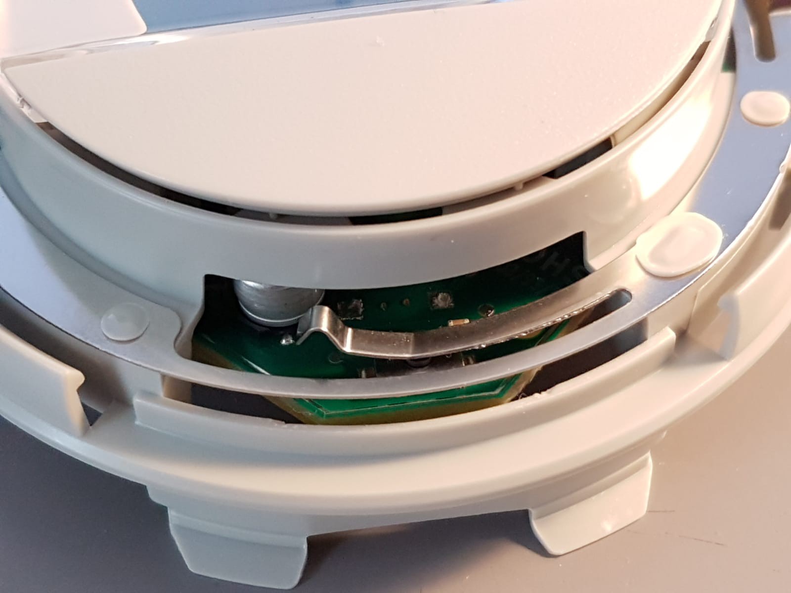
Detail of the switch under the lever when partially assembled (plastic ring missing):
The hardware mod:
For each of the switches, I added an in-series 1K resistor, and connected my microcontroller directly to the original Atmel CPU output. I figured out they'd never have those pins in low-Z, so it shouldn't be a problem.
I did this the ugly only way, cutting the existing PCB track with a knife, and soldering my resistor in the proper place wherever I could.
Reading the set point:
As you can see in the video, the latency is surprisingly low considering the amount of moving parts: ESP8266 > WiFi > Mosquitto > Node-RED > Home Assistant > WifFi > Frontend on Android chrome
One MQTT Message is sent with every encoder step. Admittedly that is a bit of an overkill as the message could be sent after a second of the value being stable, but this lets me brag about it.
The encoder is read using this Arduino library:
https://www.pjrc.com/teensy/td_libs_Encoder.html
I kind of regret not going the CLion/cmake way with this project. I wanted to give the Arduino IDE a try since this was "a quick thing" and the Wemos board is directly supported; I can't help it but to be really disappointed with the IDE. No autocomplete and no refactoring tools in 2020? Feels like programming on Notepad.
Setting the set point:
Things get a bit more complicated now. To set the set point we need to switch the encoder pins to OUTPUT mode and drive away. However, the initial phase has to be the real one, and the end phase... too. This is because as soon as we release the pins by setting them to INPUT, if their state is different from the real switch state, the thermostat will register additional unwanted changes.
Fortunately for us, when the thermostat wheel is rotated past the minimum temperature of 5 degrees, it just ignores any further steps in that direction. We can exploit this to keep "rotating" the encoder past that limit, and then keep going until the phase mismatch counteracts the mismatch that our target set point would produce. After resetting to the minimum, we want a phase that "lags" as much as we would be ahead of the physical phase after applying our new set point.
Note that the thermostat goes from 5°C to 30°C in 0.5°C increments, so our encoder values go from 0 to 60 respectively.
To reset the thermostat to a known-good position, we decrement 80 steps. 80 is an arbitrary number that is both multiple of 4 (so an in-phase change) and bigger than the total amount of 60 steps. Then we add the modulo 4 of the amount we have to move forward later. 4 being of course the four phases of the quadrature encoder.
80 + (requestedSetPoint % 4)
This guarantees that will be at the minimum and out-of-phase, behind by exactly negative requestedSetPoint % 4 steps.
// Move CCW, enough to overflow but leaving the phase in such way that
// moving to the set point will result in the phase unchanged.

int resetSteps = 80 + (requestedSetPoint % 4);
for (i = 0; i < resetSteps; i++) {
    ...
    phase = (phase + 3) % 4;
    setEncoderPhase(phase);
    delay(ENCODER_DELAY);
};
Then we simply "twist" the knob clockwise to reach the set point.
// Move CW so to reach the set point, the phase after this will
// be the same as it was before resetting, matching the state
// of the real encoder switches.

for (i = 0; i < requestedSetPoint; i++) {
    ...
    phase = (phase + 1) % 4;
    setEncoderPhase(phase);
    delay(ENCODER_DELAY);
}
This will advance the phase in requestedSetPoint mod 4, but since we were out of phase by exactly that negative amount, we end up back in phase. We can now safely set the pins back to INPUT mode without unwanted steps being generated.
Connecting this with the rest of the world:
NodeRED gets notified of set point changes and can also set the thermostat. The NodeRED flow should be self-explanatory if you played around with it. Events are forwarded to whatever is controlling your heating, in my case, home-assistant (and Alexa) via my other project: My OpenTherm interface. The NodeRED flow is in GitHub (see this project's links).
At the very end of this project I decided to also try a serial (good old RS-232) link from the microcontroller to the Raspberry PI, as an alternative to WiFi+MQTT. Both versions of the firmware are in different repositories. (also on the project links)