To speed up the propagation time of the inverters in the ring-oscillator further, I built up samples with smaller base and collector resistors.
Rb
Rc
Sample 1
360 Ohm
2.4 kOhm
Sample 2
180 Ohm
1.8 kOhm
Sample 3
180 Ohm
470 Ohm
The figure above shows the relationship between supply voltage and oscillator frequency. Reduction of both base and collector resistor increases speed at the same voltage. It is somewhat obvious since availability of more current will allows faster switching up to the point when the saturation charge storage limits the turn-off time. Since the PMBT2369 is engineered to reduce charge storage time, it increases switching speed up to a fairly high current. However at some point this is not sufficient anymore and the speed begins to reduce again. This is visible for Sample 3 (Rc=470, Rb=180), which has a maximum at around 3V. Also sample 2 starts to get slightly slower beyond 8V.
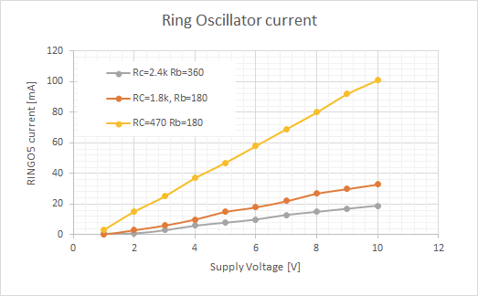
This trend is confirmed when plotting supply current vs. voltage. There is a big gap between sample 2 and sample 3, I probably should have added settings in between...
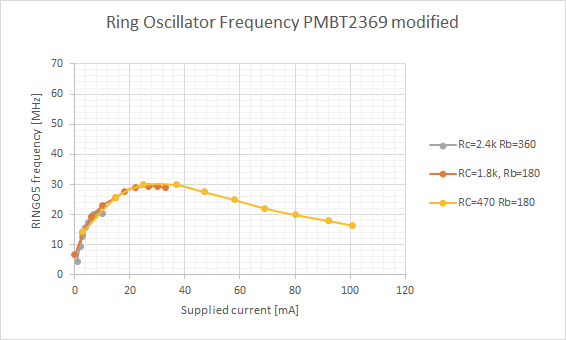
Things get much more interesting when plotting the ring oscillator frequency versus supply current. It shows that all samples follow the same relationship, so that supply current is the only governing factor to control inverter propogation delay.
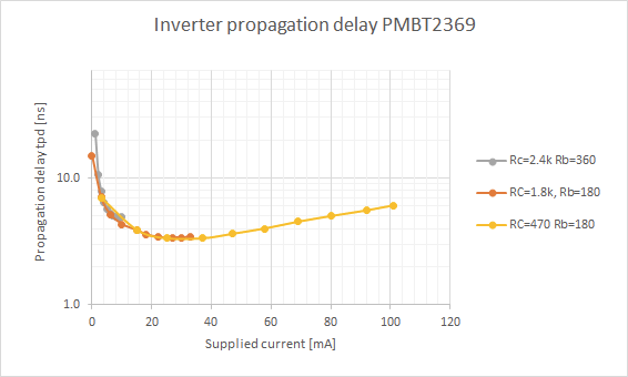
Calculating the propagation delay from the ring oscillator frequency shows that a minimum tpd of around 3.5 ns is achived at around 30 mA of supply. Since RTL gates only draw current when their input is "high", only half of the six gates (5 ringo + 1 buffer) are active at any time. This means that the bias current per gate is approximately 30mA/(6/2) = ~ 10mA.
It appears that this is smack dab on the operating point settings that are used in the CDC6600: It sits at Ic=10mA, Ib=1mA with a maximum tpd target of 5ns. The CDC6600 uses a supply of 6V and apparantly Rb=150 Ohm, Rc=680 Ohm for fan-out of 1. This is in between the resistor settings in Sample 2 and Sample 3.
So, in conclusion: It seems we can recreate the timing properties of the ancient CDC6600 using components that are still available today. However, this also requires bias current settings as high as those used back in the 60ies...
Yes, that should be interesting. My guess is that it is slower than the PMBT2369, because it is not optimized for saturation switching. See also my results for the HF-transistor.
Yes I remember these but I also remember seeing in the datasheets that these types of transistors are optimised for switching at a given current point. That's why your last curves "ring a bell" :-)
Yes, indeed. I guess the high supply voltage in the CDC6600 was also chosen to be less susceptible to droop. If you have a more stable power supply it should be possible to reduce supply.
Actually it's crazy, basically all of the headroom beyond the logical high level (1.2V) is burned as waste energy in the resistors. Thats (6V-1.2V)*10mA/2= 24mW per gate! Only 6mW are actually needed for the switching.
 Tim
Tim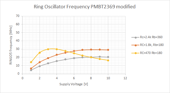
Discussions
Become a Hackaday.io Member
Create an account to leave a comment. Already have an account? Log In.
I should make a similar measurement with the BFS480 :-D
Are you sure? yes | no
Yes, that should be interesting. My guess is that it is slower than the PMBT2369, because it is not optimized for saturation switching. See also my results for the HF-transistor.
Are you sure? yes | no
Yes I remember these but I also remember seeing in the datasheets that these types of transistors are optimised for switching at a given current point. That's why your last curves "ring a bell" :-)
Are you sure? yes | no
10mA is quite a lot...
But overall power could be reduced by using lower power supply voltages. Maybe even use a standard 3.3V PSU ? Rc=470 would then be the sweet spot :-)
Are you sure? yes | no
Yes, indeed. I guess the high supply voltage in the CDC6600 was also chosen to be less susceptible to droop. If you have a more stable power supply it should be possible to reduce supply.
Actually it's crazy, basically all of the headroom beyond the logical high level (1.2V) is burned as waste energy in the resistors. Thats (6V-1.2V)*10mA/2= 24mW per gate! Only 6mW are actually needed for the switching.
Are you sure? yes | no
Fortunately today we have PoL regulators :-)
Are you sure? yes | no