 Nicholas Stedman
Mocoder overview
Mocoder is a small breakout board for the AS5600 magnetic encoder IC, along with an enclosure and a magnetic spindle, so it is a complete magnetic encoder. You can read the position of the encoder out over i2c, or simply as an analog signal from an ADC. Additional features are also available over i2c, and AMS have provided an Arduino library for i2c interfacing:
I'd also recommend checking out the datasheet for the AS5600:
http://ams.com/eng/Products/Magnetic-Position-Sensors/Angle-Position-On-Axis/AS5600
Here's a video of mocoder being read from an Arduino over i2c.
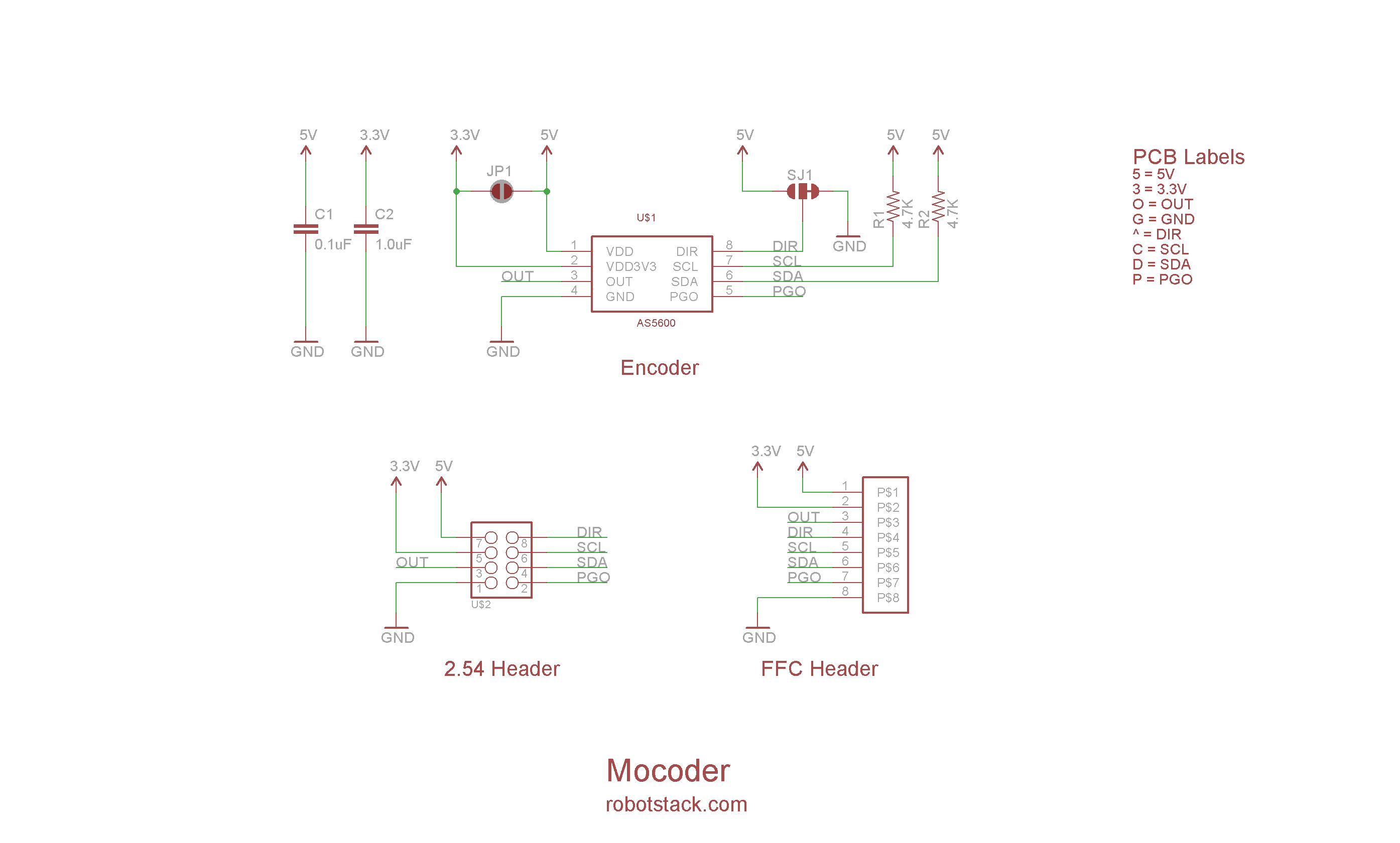
Schematic
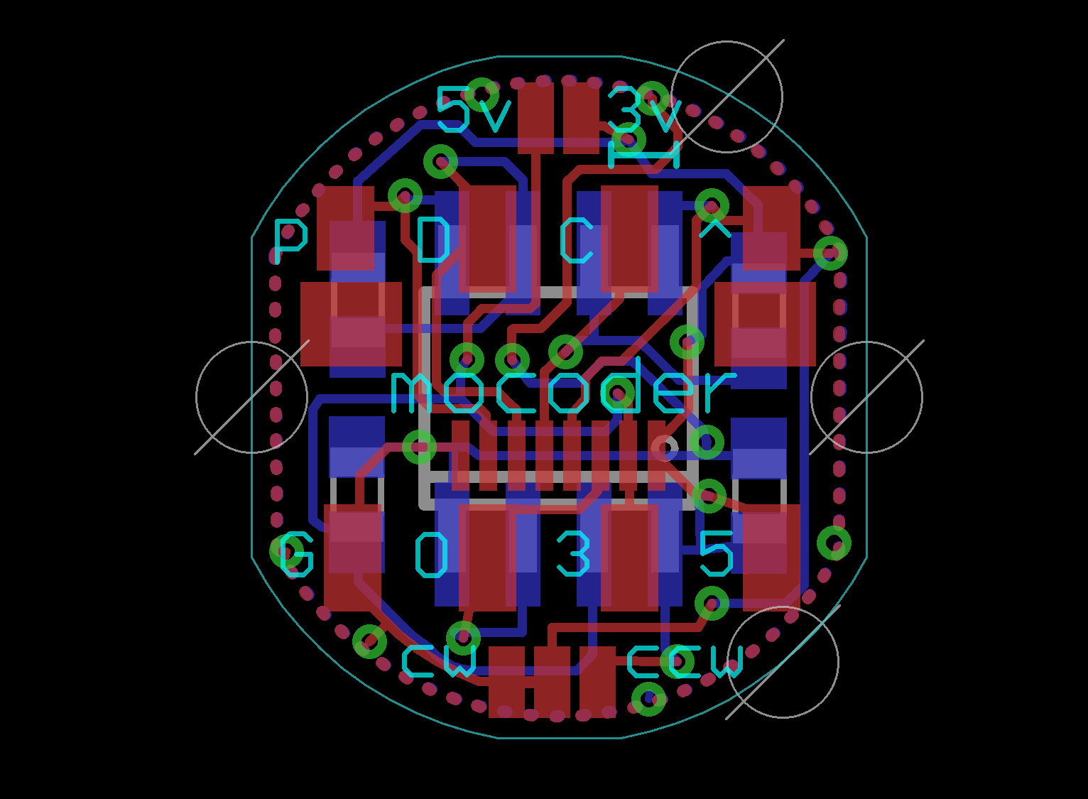
Layout
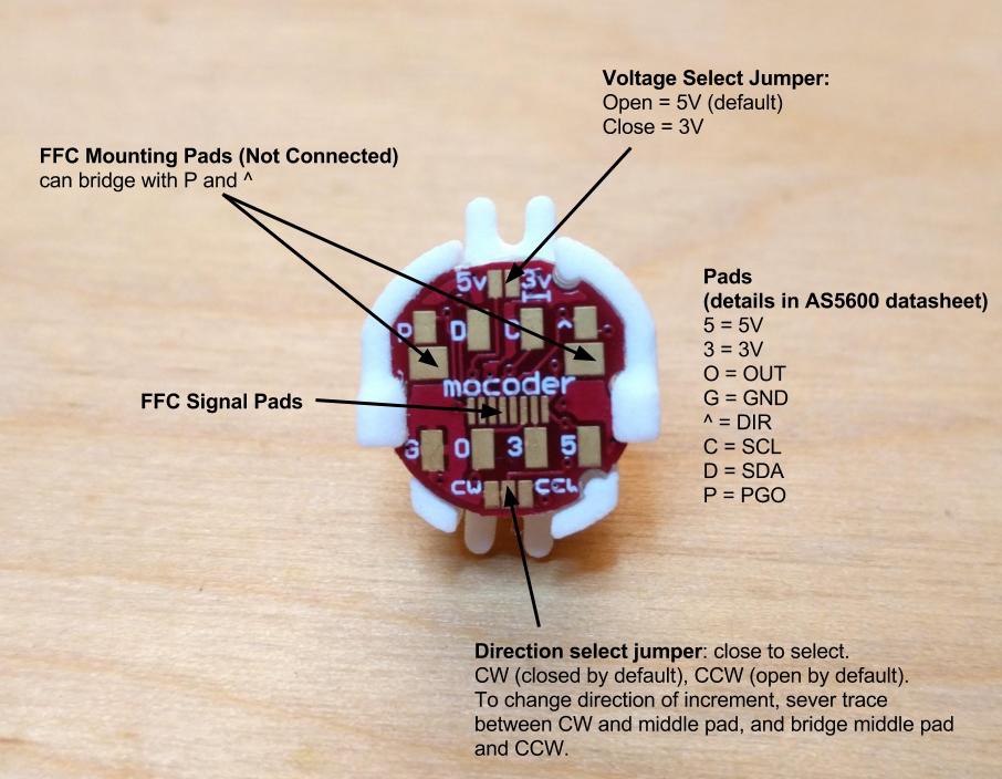
Legend
Some things to note.
- The 2 pin jumper allows you to select between 5 Volt (default) and 3.3 Volt operation. For the latter solder the jumper closed, and then supply 3.3 Volts to the pin labeled 3. For 5 Volts, leave the jumper open and supply 5V to the pin labeled 5.
- There are already 4.7k pullups on the i2c lines.
- The 3 pin jumper allows you to select between incrementing or decrementing values as the magnet spins in a particular direction. To change it, sever the existing trace between the center pad and the CW pad, and solder between the center and CCW pad.
- There's a footprint for an 8 pin FFC connector on the board. It is unpopulated by default, however this part is known to fit if you want to add it yourself.
- The FFC footprint has two Not Connected mounting pads. It is okay if these come in contact with the provided pin header or your own wires.
Soup up your Servo with Mocoder
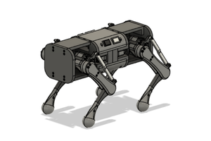
You can replace the pot in your RC servo motor with Mocoder to allow it to turn continuously and have position tracking. You read the position of the encoder from a microcontroller and move the continuous servo until it arrives at the desired destination. The microcontroller also allows you to add some intermediary intelligence. For example, you can move the motor with your hands and sample the position. Then play back these positions. Check out some examples in the following videos.
Example 1: Programming a robot by hand
Example 2: Robot servo in a gearbox - (some overlap with previous video)
Example 3: Robot servo controlling a linear slider track
Mocoder has been tested and is known to fit and work with the following servos:


 Remove the top of the case. Be careful not to drop the gears, as they are no longer held in place.
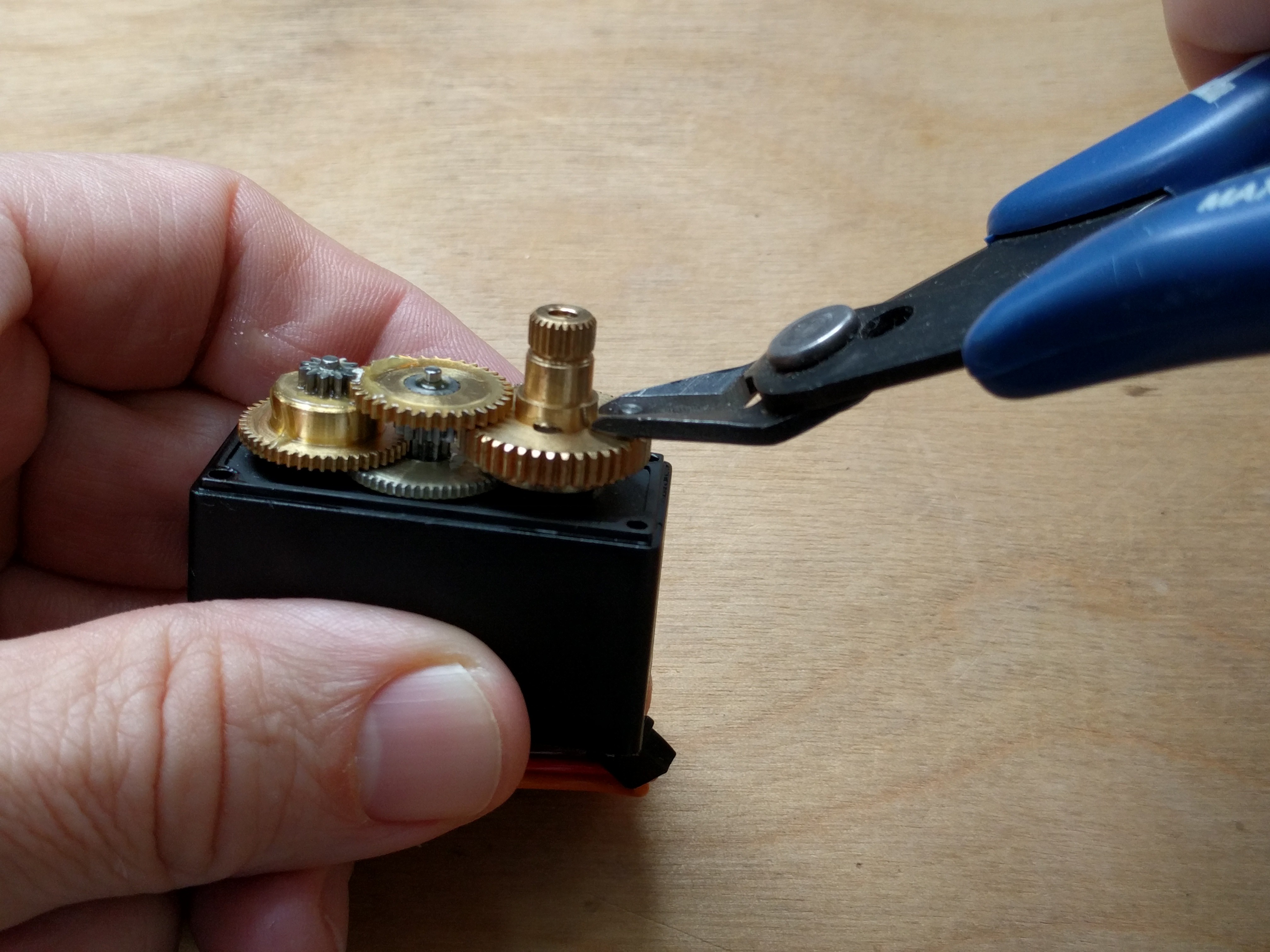
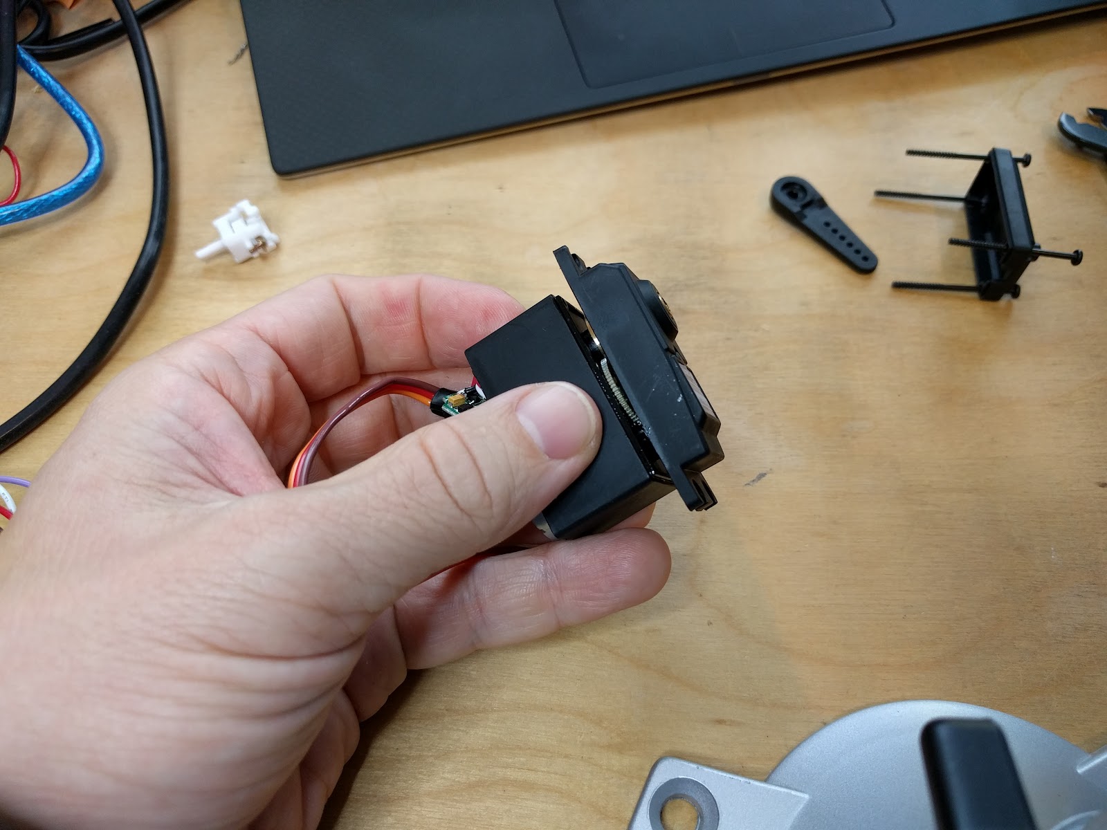 Remove the stopper pin from the pinion gear. Try using wire snippers to grip the sides, and using the tip of the snippers as a lever.


 Aaed Musa
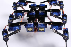
 icstation
 Harri Ohra-aho
 Norbert Zare
Hi
I decided to try your project and ordered a sensor. But I have found your link to the arduino library does not work. Can you provide the library locally or a new link? The senor is pretty much useless if I cannot find a library.