 Jacques Gagnon
SEGA made several revision of the MD/Gen board (9 for model 1, 7 for model 2) and each of then affect the AV output in different way. On top of that the Sega CD and 32X add-ons add their own audio and video.
I will document here my experience with my own Model 2 VA0.
Original circuit
Audio path
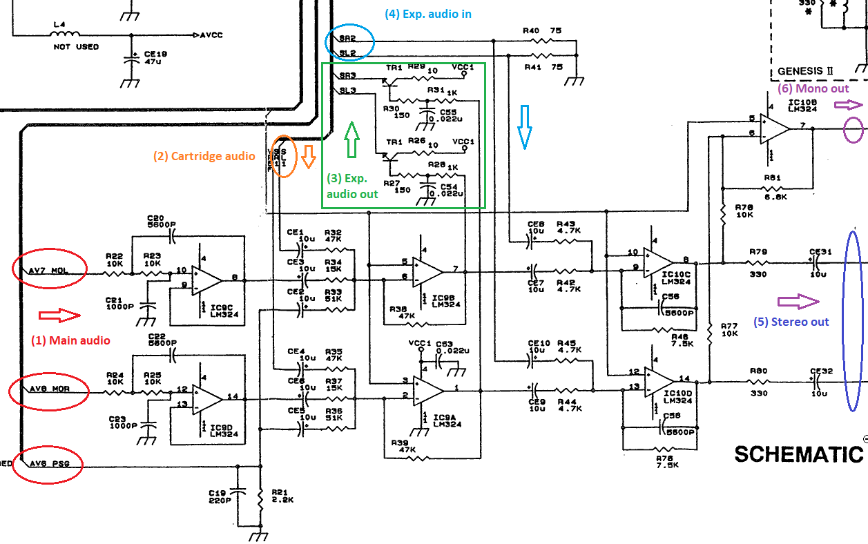
The cartridge port audio (2) [32X] get first mix with the system main audio (1), this is sent to the expansion port audio output (3) [Sega CD]. Then the expansion port audio is mixed in (4) [Sega CD] and everything is output on the Mini-Din 9 AV port (5). A last stage also mix the 2 audio channels for the mono output (6) also available on the AV out. The 32X simply passthrough the audio outputs from the main system AV out to it's own AV out.
Video path
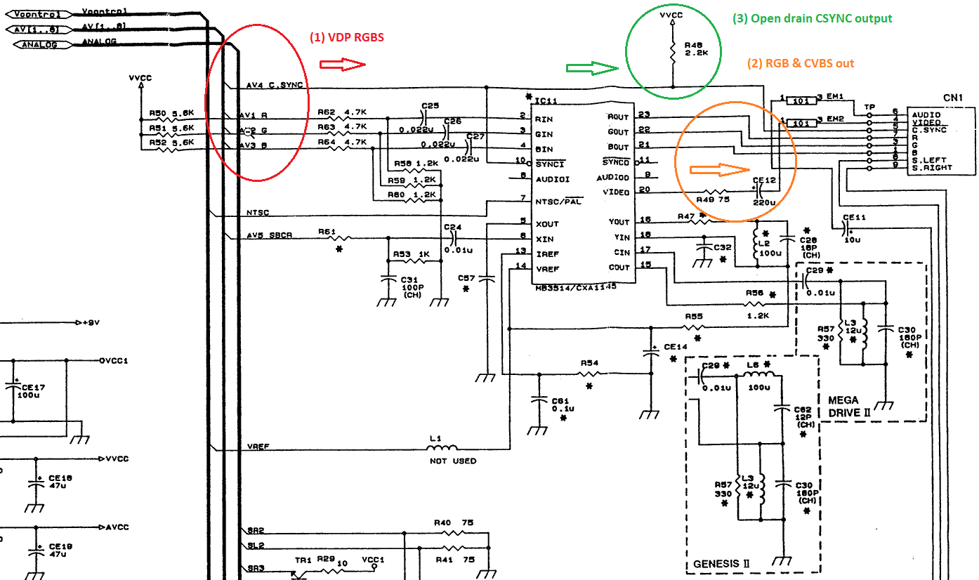
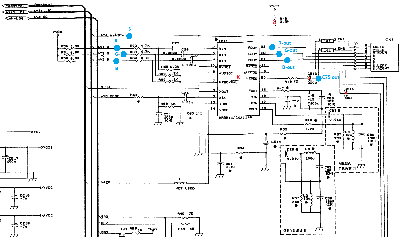
RGBS 5Vpp video from the VDP (1) goes to the video encoder which drive the CVBS and RGB on the AV out (2). An important note is that the RGB line are missing the 75Ω and 220uF capacitor which need to be added in the cable (more on that later). Also the CSYNC output is from the VDP directly (3). It's an open drain output that is not advised to use for cable without a proper driving circuit.
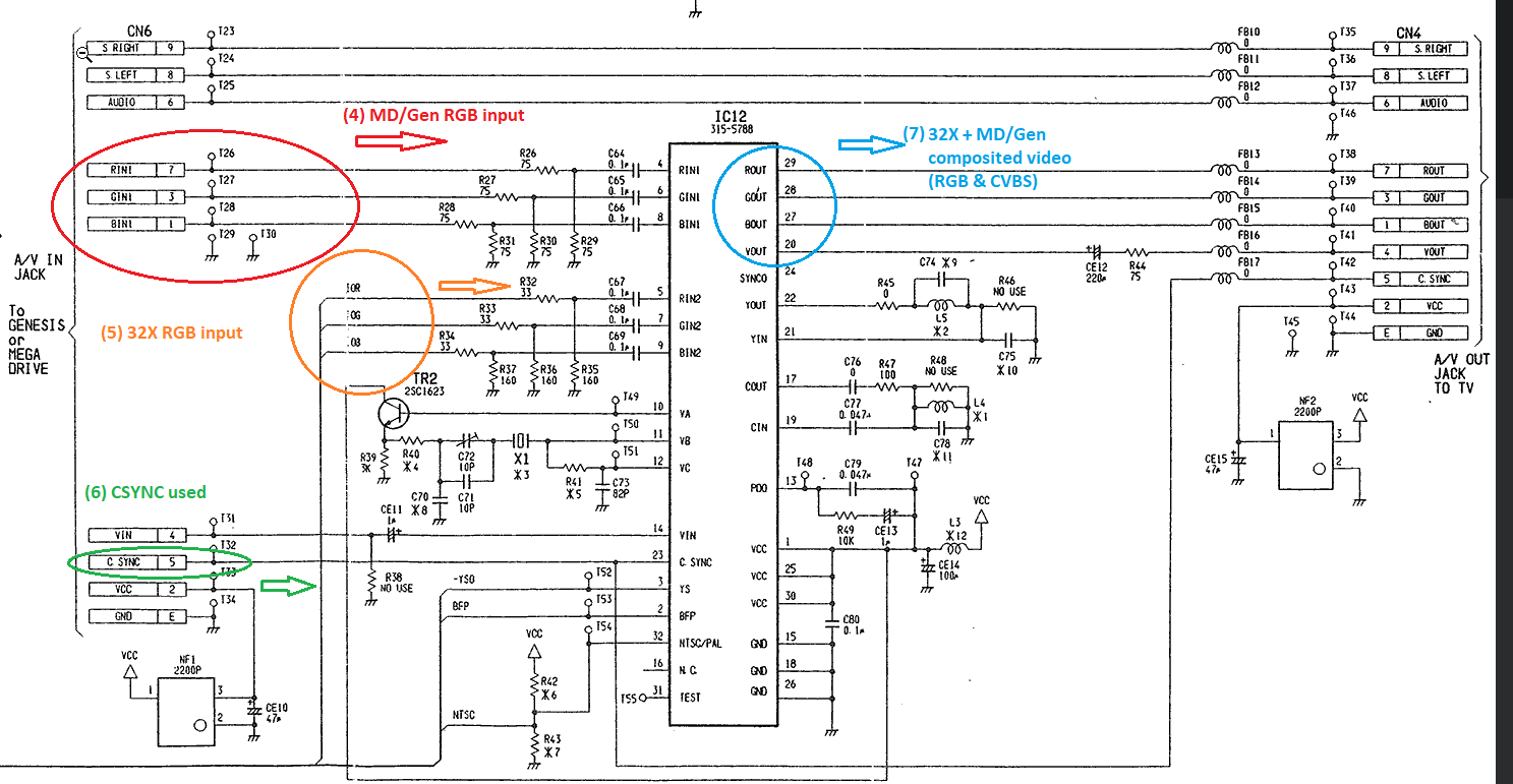
The 32X use video compositing with alpha channel which allow to superpose the main system VDP analog output (4) with it's own video output (5) (either below or over). Using a straight cable connection between main system AV out and it's own AV input it use the RGB and CSYNC lines (6). The composited video is output the same way as the main system with missing component on the RGB channel (7). The CSYNC is passthrough to the 32X AV out.
Fixing issues
Buzzing sound on video white to black transition
This is often result of bad cable construction. I had a cheap cable from ebay with that problem. RGB lines 75Ω resistor were placed at the SCART connector end, TTL CSYNC and no individual shield for each line. This caused parasitic capacitance from Video to go onto the audio create the buzzing sound.
Solution would be to make sure the resistor are place inside the Mini-DIN 9 plug on console end and using cable in which each signal is shielded individually.
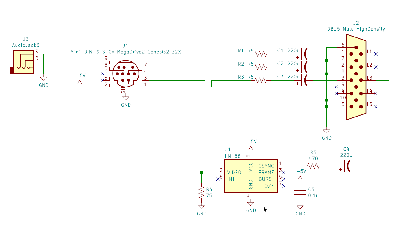
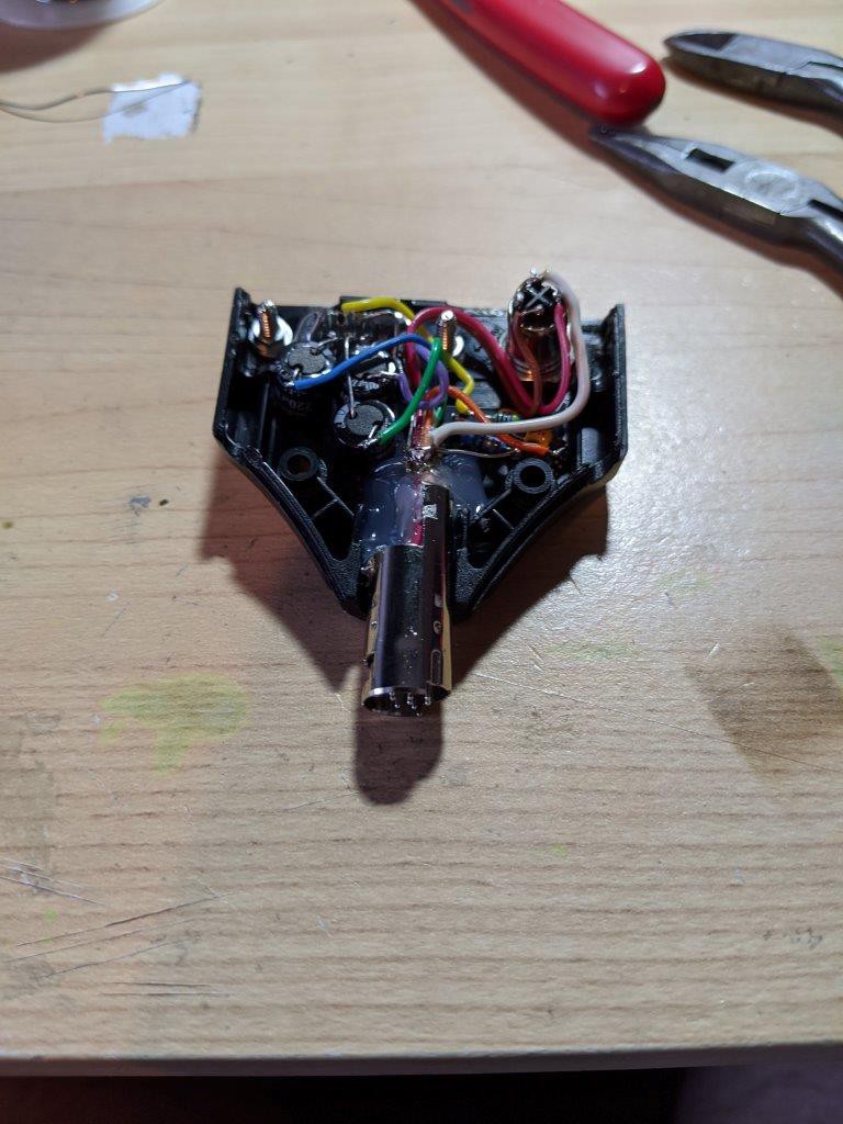
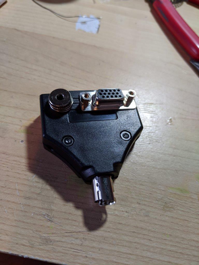
For my setup I made a small Mini-DIN 9 to DE15/TRS to be able to use regular cable.
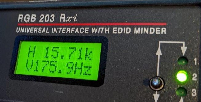
Harmonic on CSYNC?
I haven't seen this one mention online other than MD/Gen got a bad sync. On my newest Extron RGB 203 (w/ EDID) sync processor I see the Vertical frequency detected as 175Hz!! That look close to the 60Hz 3rd harmonic. My older RGB 203 don't see the sync at all! Maybe a notch filter would help. XRGB3, XRGB-mini & TV handle the sync fine however. This still need to be investigated...
Video jailbar
The jailbar come from interference from the chroma subcarrier as the pcb trace are close to the RGB output trace. If you don't need functional composite video you could just lift pin 6 of the video encoder to resolve this issue.
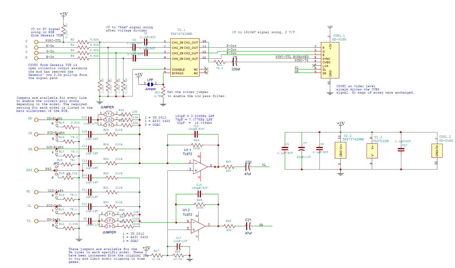
Another solution is to perform an RGB bypass mod were the RGB is taken directly from the VDP output as pass through an THS7374 video amp. See Triple-Bypass mod below.
Restoring model 1 audio balance/level
Later revision don't quite sound like the original one. Their is 3 category of MD/Gen when it come to audio.
- The earlier one using discrete YM2612 chip.
- YM3438 integrated on same ASIC as VDP.
- YM3438 integrated on the Genesis-on-a-chip (GOAC).
Fixes for audio evolved over the years.
First you had the Crystal Clear Audio Mod by Tiido in 2009 that specific for model using the ASIC YM3438.
Then the MEGA AMP by Ace in 2014 for all version. Followed by MEGA AMP 2.0 update in 2017.
The Triple-Bypass mod by db-electronics merge together the mega amp 2.0 with the RGB bypass mod.
The Triple-Bypass V2 mod by TianFeng offer a solution for all model revision with one PCB and fine tune the audio to be as close as possible to what a VA3 model 1 would output.
Triple-Bypass V2 on Genesis 2 VA0
Let mod now! Doing the mod as I did will replace the CVBS ouput with 75Ω CSYNC, will remove mono audio output, and remove the audio output going to the expansion port. All of which is not needed while using RGB and audio from the Mini-DIN output.
If you purchase pre-assembled board chance are they soldered a Mini-DIN9 on it by error. So the first step will be to take it out. Braid and ChipQuik will help as the connector fit on the PCB is quite tight!
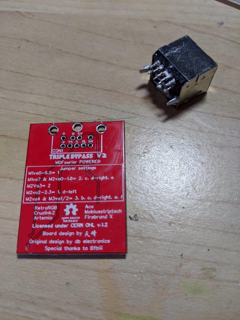
Then you need to set the jumper on the board to match what your model need base on the chart on the PCB back. In my case for model 2 VA0 I had to solder jumper 2 for each audio channel and jumpers c, d-right and e.
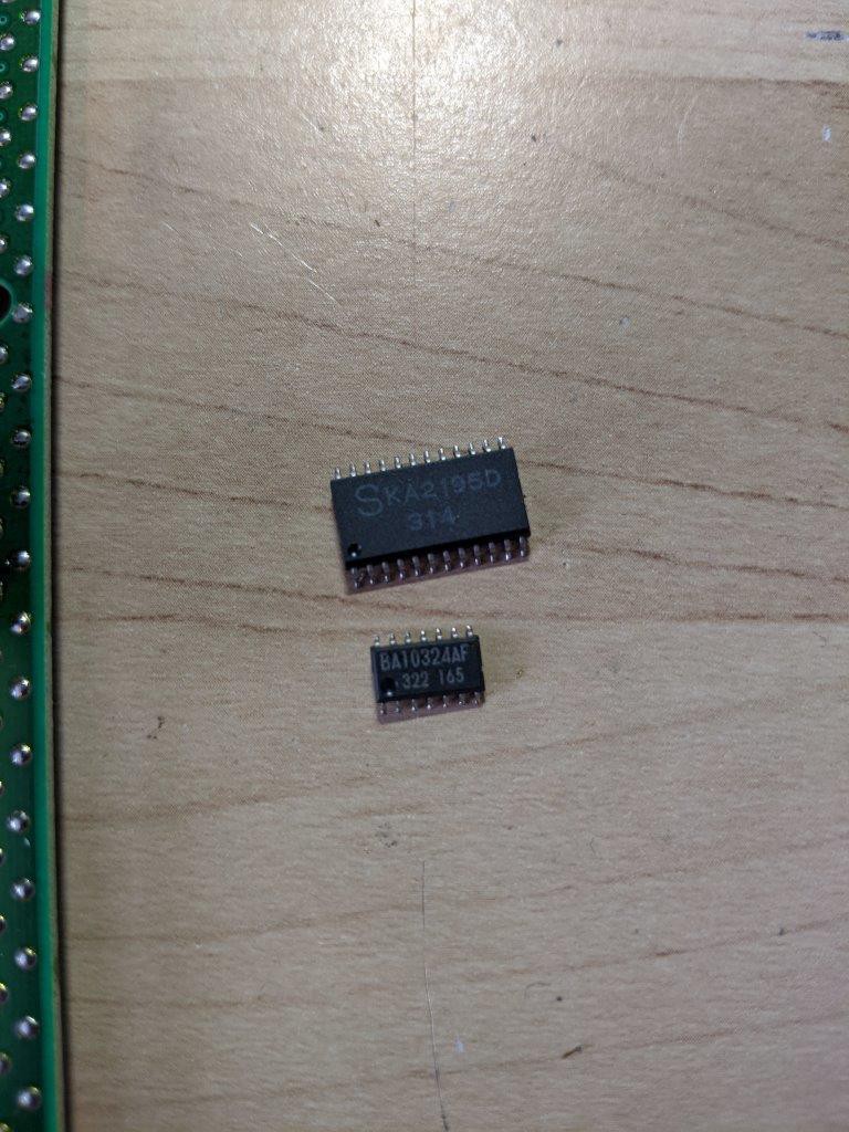
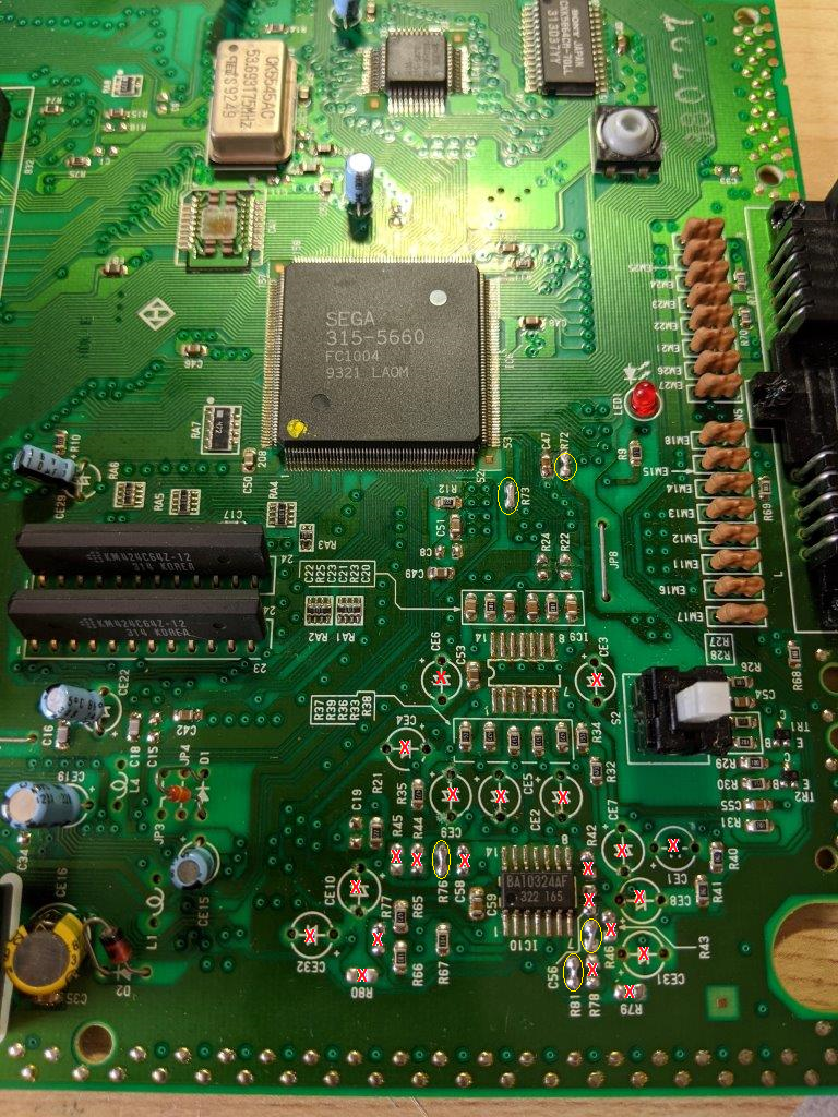
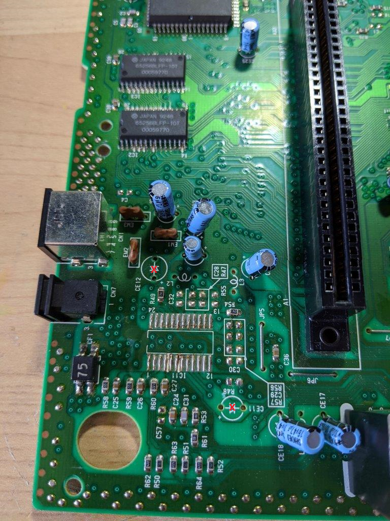
Now we got to remove a few part from the PCB. First I remove the video encoder (IC11) and one of the quad opamp (IC9) with hot air. We got to keep IC10 as one of the opamp is used by the reset circuit. We will setup the 3 unused opamp to follow VREF to keep them in a stable state.
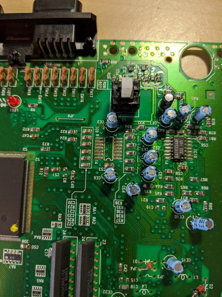
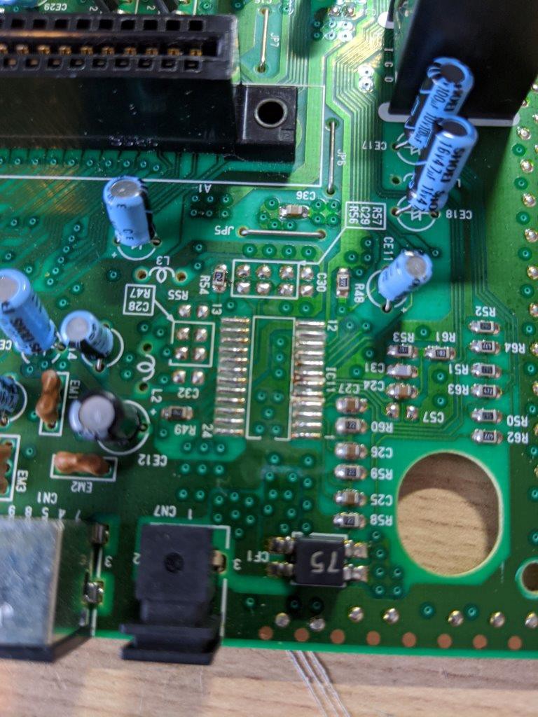
Now let remove the unused electrolytic capacitors to make a bit of room to work and avoid future leaks. Remove CE1, CE2, CE3, CE4, CE5, CE6, CE7, CE8, CE9, CE10, CE31 & CE32 in the audio amp area. Remove CE11 & CE12 in the output area.
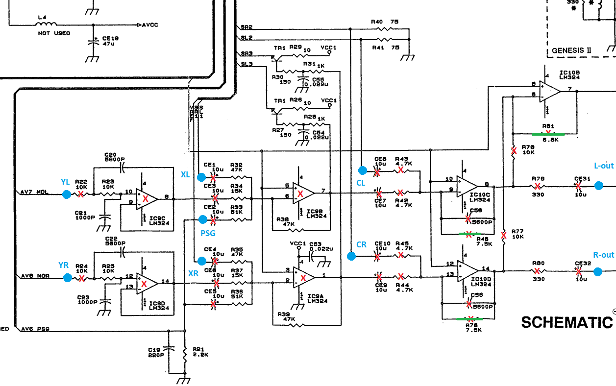
In the output area remove the CSYNC pullup resistor R48 as the mod board include it's own. In audio amp area remove resistors R22, R24, R42, R43, R44, R45, R46, R72, R73, R76, R77, R78, R79, R80 & R81 and ceramic capacitors C56 & C58.
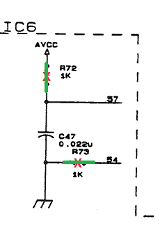
Now bridge R72 & R73 (I couldn't find the rational for this, I guess it improve audio somehow by giving the YM3438 direct supply?? Leave a comment if you got more info!)
Bridge R46, R76 & R81 to put the 3 unused opamp in VREF follower configuration.
Finally, we hook up the mod board. I placed it on top of the VDP ASIC with double sided foam tape as most connection are in that area. You could in theory install it under the pcb directly on the Mini-DIN-9 pin but in my case the connector got 5 shield pins rather then the 3 this mod board got so it wouldn't fit without some work I didn't feel like doing at the time :).
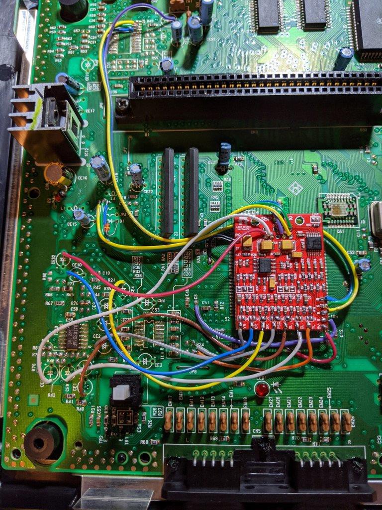
I connected GND and 5V to the nearest power plane. Connect the RGB output to the video encoder (IC11) pas 23, 22 & 21 respectively.
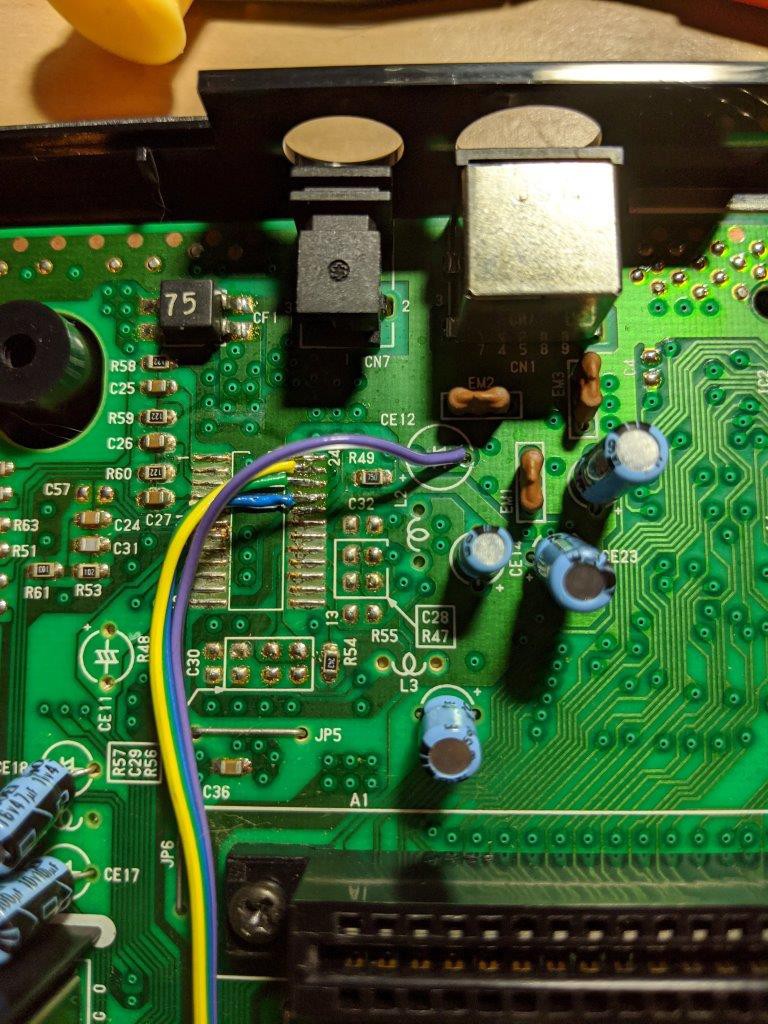
Connect 75Ω CSYNC to the old CVBS output via the negative pad of CE12. The easiest point for the RGB input is the vias near the unpopulated L4.
Connect (S)ync to the pad next to C8 label (unpopulated). Connect YL to R22 label side pad and YR to R24 label side pad. All the following audio connection goes on the negative pad of the following electrolytic capacitor. CL to CE8, XL to CE1, PSG to CE2, XR to CE4, CR to CE10, L-out to CE31 & R-out to CE32.
Your Megadrive or Genesis should now sound and look amazing :) .
Discussions
Become a Hackaday.io Member
Create an account to leave a comment. Already have an account? Log In.
hello I have a VA0 genesis 2. When I first got it my tv would pick up a signal but the screen would be black and there was a buzzing noise. I nievely thought I could fix these issues wit a triple bypass mod. I followed the above guide and now my tv dosent even get a signal. I’ve checked continuity from the cpu to the mod board and from the mod board to the din connector. Everything seems correct (except maybe that I get continuity between the 75 ohm pin and ground) any ideas?
Are you sure? yes | no
Hi there! Love this guide. It worked great on my VA0 pcb. Can confirm that this works on a VA1.8 pcb as well. Thanks so much!
Are you sure? yes | no
Hello, I have a questions regarding the removal of IC11. I suppose watching yout images that is safe to remove the small capacitors and resistors around it but you only mention to remove the electrolitic capacitors, I'm modding an europeand md2 va0 and is slightly different than this, that's why I want to be sure. Thank you.
Are you sure? yes | no