Close
0%
0%

Retro Slide Project Beamer Conversion

Converting 60-year-old German technology into a beamer, Retro-Style.

Similar projects worth following
162 views
This project is a follow up to my other project https://hackaday.io/project/170585-retro-slide-projector-green-edition - we will now add a Beamer function.

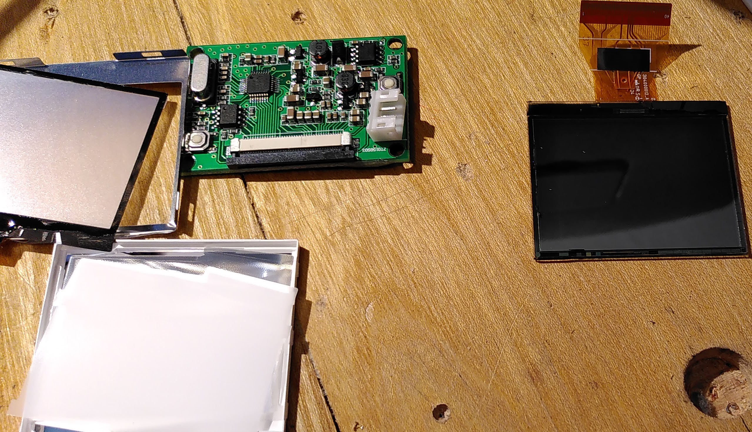
Disclaimer: we will not build a 4K/HD Beamer here but convert a small display into a display for an old slide projector. Don't be disappointed by the quality it will deliver. It's 320x240 in resolution and the colors are not calibrated. Best outcome is with black and white material.

Regard this as an art project, but rather not as a beamer replacement. Have fun!

Please note that I am not liable for any damage occuring from this project. You are working with high currents, high temperatures and LEDs that might damaga your eysesight. Only work on this project if you know what you are doing!

  • 1 × Adaruit 911 2,0" PAL/NTSC Display
  • 1 × FFC FPC 40pin 0.5mm Pitch Ribbon Flat Cable ZIF+ Adaptor extend connector you need a cable and a double-connector
  • 2 × M3x10 screws with nuts
  • 1 × DC-DC-Converter (12V -> 5V) optional but recommended
  • 1 × slide yes, we need an old slide for this - or a 3D printer to print

View all 6 components

  • 1
    Remove the slide holder (and get safe)

    At first, identify your slide projector: if you have an old model without an airflow channel in front (see picture), you might need to be creative to get the cable connection running in a nicely manner. If you can, go for a newer version.

    To remove the slide holder from the projector, just move it upwards.

    Now we take a very important safety measure to stop your display from being destroyed by ripping the flat cable in half by accidently moving the slider. Do it now, or you will regret it later. Pull the slider in either direction so it is in an end position. Now drill a hole (3mm) through the holder on the other side. I drilled two holes to make it look even, but you need only one to keep your slider fixed.

  • 2
    Disassemble LCD screen and remove backlight

    The LCD screen used for this project is a 2.0" PAL/NTSC panel from Adafruit (Adafruit 911). You need to remove the backlight in this step.

    Be very careful with the display, especially with the film cable, it will rip easily.

    If still connected, remove the display from the board by opening the connector. Detach the display.

    The display has a silver metal cover. Remove this cover. Remove the white backlight carefully. You have to cut the smaller film cable that is connected to the larger one by two large soldering spots (it's for the backlight power).

    Remove all foils that come down in this process. You now should have a simple shine-through display. It has a matte side and a silver side.

    left: leftovers, middle: PCB, right: display (with flexi cable)


    A word of warning about the Adafruit 911 displays: these gave me some (expensive) headaches, so I will share my experience with you:

    • respect the warning on the website: the film cable is absolutely delicate
    • the devices work with input voltage of 5V to 12V
    • there are two buttons on that PCB (see picture): one is next to the white connector, the other one is on the opposite
    • the one next to the connector rotates the screen
    • the one on the opposite changes the contrast of the screen
    • both buttons keep their settings after a restart
    • obviously, there are different versions of the PCB AND the display around: the website states, there is only one button (to change the contrast). This is not true for the current PCBs, they all have two.

    I made the mistake of interchanging displays and PCBs, which turned out to be a nightmare. Do not do this! The PCBs and displays seem to have different specs, I fried the power regulator of one PCB with 12V input voltage, one display did not rotate and had image distortions, for example. After I found out about this, I compared three PCBs with each other and all of them had different parts soldered or some parts not soldered.

    You should make sure your display is ok with a "dry-run" before dismantling it (or shelving it for later use). As a video-source, you need a RCA (FBAS) device. Canon EOS cameras have a RCA (FBAS) output. Just note, that it turns off very quickly. But for testing, it's ok.

    If your display does not rotate, you will be very limited in the devices you can connect as it needs to be able to rotate the RCA/FBAS ouput itself. The Raspberry Pi can, but most other devices can't!

  • 3
    Create "fake" slide and mount display

    Take an old/unused slide and open it (you should use a very simple type that has no hinge). Measure the size of the slide and cut out a piece of cardboard.

    yes, it's as easy as that

    Now take the display, center it on the cardboard (so the display is in the center) and cut out the cardboard so you have a simple spacer for the slide.

    Take the cardboard, glue it to one side of the slide, put the display in and glue the other of the slide on top (you don't need to destroy the slide, I did it by accident).

View all 7 instructions

Enjoy this project?

Share

Discussions

Similar Projects

Does this project spark your interest?

Become a member to follow this project and never miss any updates