Close
0%
0%

stm8-easymon

Use 7 segment displays to monitor numbers of any kind

Similar projects worth following
A deep-dive tour through a single stm8s103f3 project with an overwhelming quantity of details. I wanted to collect all the information I had to find here in one place so it might provide some enlightenment if you are stuck on a similar project.

Introduction

I'd like to share how I use 7 segment displays and STM8 boards to monitor/display numbers of any kind.  This started out as a project for work, but quickly escalated to something a little more interesting, and challenging, and maybe even useful.  So here's the story, and I'll try to keep it short. And I'll even try to put the good details up front so you don't have to wait.  

This project rests on the shoulders of others and it's not at all 100% my own creative doing, but a lot of this may bridge the gap for some of you out there who want to do this type of thing, so I'm sharing.  I'm pretty jazzed about this and I hope you are too.  Some preliminary thanks to Thomas for sharing the bulk of the information I've relied upon and his super awesome willingness to prod me in the right direction.  Thomas also has a github site for stm8ef and other projects you can find here on Github.  The site Bare Metal Programming and a great blog get some serious read time credit to lujji!  A great many good vibes to Robin for this page https://maker.pro/custom/tutorial/using-gpio-on-stm8-microcontrollers and all that good info.  A huge thanks to the Sduino Project and all the detailed info about the blue pill board.  I welcome feedback, comments, and corrections regarding this page.  

Hardware

The STM8 comes in a variety of shapes and sizes, and Thomas has covered a huge swath of them in great detail and has provided a lot of more generalized details about the STM8 line and the devices that you can find out there.  I'm intending to cover only just this one, because it's popular, inexpensive, easy to use, and what I have on hand at the moment that works for my development needs for the project I started out to finish.  I'm accomplished the task a few different ways, but I am after a better way, always.  I'm using the STM8S103F3P6 in a board that brings all the pins out to the edge so you can get at them, and you can install header pins and make it plug right into a protoboard.  I grew up in the era of Radio Shack's popular books by Forest M Mimms III, which featured many circuits, using a breadboard or protoboard, and dip chips and transistors and other small component to build a large variety of applications and educational demonstrations.  The protoboard is probably the easiest way to get this stuff built so you can play with it, adjust it, experiment with it and learn things while being productive.

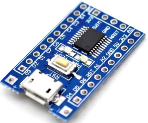
Hardware setup.  Blue Pill STM8 board for under a buck.  4-digit seven segment display.  Serial interface.  USB "swim" programmer.  Breadboard. a 10K to 25K pot and 8 limiting resistors for your LEDs (almost anything from 220R to 1K should do, as long as you've got a handful of them).  And header pins, or just some bits of the right kind of wire if that's all you've got.  The pins are cheap, buy a bunch.  And a linux box (ubuntu worked well), and you might get a nice multi-port powered USB hub to make things easier on yourself.

Software

Rev 1: I used the Arduino IDE and the "sduino" bits that I found out on the web.  This let me write in C and allows for reasonably readable and easy to write code, and a binary of about 5200 bytes.  I'm sure I can do better, the things only got 8K, and I want room to move around in there...

Rev 2: ... So I try my hand and cobbling it together in SDCC from source (and librarie files borrowed from all over the place) on my linux box.  I borrowed a little #define macro here, and a little idea about a smarter way to do the thing I was doing there, and a little speed increase by trying more direct GPIO over here, and pretty soon, I'm looking at a reasonable facsimile of a running hunk of code on the proto and it's more configurable, faster and only about...

Read more »

stm8s103f3.jpg

The STM8S103F3 "blue pill" breakout board. USB power connector (no data connection... bummer) provides 5V operation. The swim connector can reprogram it and also power it via 3.3V if you run a ground wire from the swim ground to Vss pin 7. My swim ground header pin does not seem to be connected to anything else on the board.

JPEG Image - 39.34 kB - 04/09/2020 at 15:25

Preview
Download

  • 1 × STM8S103F3 blue pill breakout board
  • 1 × USB Programmer (swim)
  • 1 × USB Serial Interface
  • 1 × breadboard/protoboard
  • 1 × small components (8x 100 ohm resistors, 1x 25K linear pot)

View all 7 components

  • Flashing multiple images with two stlinkv2 at once

    Andrew Clapp04/27/2020 at 19:47 0 comments

    Multiple Programmers!  I have a project where I need to have two STM8's with different code on them in the same circuit.  So, I wanted to build a programmer that could simultaneously put code on two STM8's at once using two USB plugged stlinkv2 programmers.  The programmer is based on a raspberry pi 3 B+ and I used raspbian buster full as the OS.  It has the compliler and almost all the bits needed right out of the box.  I had to install libusb dev to build the stm8flash binary.  

    Then I ran into a snag.

    The stlink's showed up as /dev/stlinkv2_2 and /dev/stlinkv2_3 so I figured that I'd simply point the stm8flash at them thusly:

    stm8flash -c stlinkv2 -d /dev/stlinkv2_2 -p stm8s103f3 -s flash -w IMG1.hex 

    and

    stm8flash -c stlinkv2 -d /dev/stlinkv2_3 -p stm8s103f3 -s flash -w IMG2.hex 

    No dice.  The stm8flash simply flashes to the first one it sees both times.  You need to pass stm8flash the -S flag with the stlinkv2's internal serial number.  Then I had to dig in and learn about serial numbers.  I tried the usual things, lsusb -v, and dmesg, and digging around in /proc, and usb-devices and so on.  No matter where I pulled the serial number from, it was a string of unintelligible and some non-printable characters.  I could not 

    It then dawned on me that I had the source for stm8flash.  *lightbulb*  

    At line 233 of main.c (at least in my copy), I found this:

                                    // print programmer data if no serial number specified
                                    if(!pgm_serialno_specified) {
                                            fprintf(stderr, "Programmer %d: %s %s, Serial Number:%s\n", numOfProgrammers, vendor, device, serialno_hex);
                                    }

    I'm not sure how the logic is intended to be triggered to print the serial number from command line use of stm8flash.  It seems like if there is more than one programmer, and the serial is not specified, it should print them, but it did not work that way for me.  However, if you copy the fprintf() statement to outisde of the if() { }, then it prints them regardless, and you get a nice happy hexidicimal string that works with stm8flash.  Since I had my system copy installed in /usr/local/bin, I just used the local source copy to print out serial numbers and I'm sure one could probably not kludge it up like me, but I was being impatient.

    pi@raspberrypi:~/stm8flash-master $ ./stm8flash -d /dev/stlinkv2_3 -c
    stlinkv2 -p stm8s103f3 -u
    Determine OPT area
    WARNING: More than one programmer found but no serial number given.
    Programmer 1 will be used:
    Programmer 1: STMicroelectronics STM32 STLink, Serial
    Number:553F6606483F57541227073F
    Programmer 1: STMicroelectronics STM32 STLink, Serial
    Number:553F6606483F57541227073F
    Programmer 2: STMicroelectronics STM32 STLink, Serial
    Number:503F6F06483F57562156203F
    Programmer 2: STMicroelectronics STM32 STLink, Serial
    Number:503F6F06483F57562156203F
    Due to its file extension (or lack thereof), "Workaround" is
    considered as RAW BINARY format!
    Tries exceeded
    

    Now to flash the multiple images to their respective STM8's, I just run this:

    stm8flash -c stlinkv2 -d /dev/stlinkv2_2 -p stm8s103f3 -S 553F6606483F57541227073F -s flash -w IMG1.hex 

    and

    stm8flash -c stlinkv2 -d /dev/stlinkv2_3 -p stm8s103f3 -S 503F6F06483F57562156203F -s flash -w IMG2.hex 

  • Quickly Adapt Project to stm8ef-modular-build

    Andrew Clapp04/18/2020 at 17:43 1 comment

    I have been able to quickly apply Thomas's new modular approach to my project.  Thank you!  I grabbed a zip file of the stm8ef-modular-build repo and extracted it on my linux box. I have sdcc and supporting software installed there.  First I edited the board.fs and put in a little cusomization for what I needed.  This file contains the forth code you will be running at the end of your build, after the target is flashed with your new image.  If you write things to NVM here and then COLD or WIPE and start it, the newly programmed micro will now be your own custom embedded device.  By default it will display an analog input on the LEDs as a number from 0 to 1023, which you can scale how you like in the show function, for example:

    4 ADC! ADC@  1000 1023 */ . 
    

    This would result in scaling the full range of the input (a voltage from 0-3.3V or from 0-5V depending on your supply, use a regulated supply) to a number between 0 and 1000.  You could scale up from 1023 as well.

    If you're building for a different chip, edit the target.inc to reflect the correct memory layout.  I basically changed all the STM8S003F3 to STM8S103F3 (which is  really just this one line for my chip).  This is probably a bit pedantic and may not be necessary.

            EEPROMEND =     0x427F  ; STM8S103F3: 640 bytes EEPROM
    

     Pay attention to boardcore.inc when you assemble your project for pin numbers and GPIO settings.  The file globconf.inc controls some of the features you're going to use or not use.  You can turn things on and off simply here.  If you don't want a serial console, say you need to use those pins for something else, you can turn of the UART that is on those pins.

            HAS_TXUART       = 0    ; No UART TXD, word TX!
            HAS_RXUART       = 0   ; No UART RXD, word ?RX
    

    There is a README.md file in the DEMO directory, read that in addition to the top level README for all this info and more.  When you're done with your edits you type make, and if you've got all your ducks in a row, it builds the image, flashes it onto your device (that you have connected with your STLINKV2).  Say you have another terminal open, maybe with e4thcom running in it, and you've got a usb-ttl converter connected to the serial console pins on your device as well, you can talk directly to the forth instance running your newly coded environment.

    Now why would you even want do this?  The way I had to go about this before was to clone a whole board, like the W1209-CA, directory in the stm8ef repo, modify all the .fs and .inc files, and the top level Makefile to get it to work.  This was a great way to learn it, but using the modular repo is so much easier and faster.

View all 2 project logs

Enjoy this project?

Share

Discussions

Andrew Clapp wrote 04/11/2020 at 20:07 point

Thanks!  I'm just trying to give what I get.  I'm learning a ton from this project, and I imagine there are others that might benefit from a single example that is well fleshed out.  The stm8ef project covers _so_ _much_ ground that it took a good many little bits from many different places to make the cohesive picture I needed to understand it.  My goal is to really cover this one thing in depth.  It also serves as a handy reference for my aging gray cells.

  Are you sure? yes | no

Thomas wrote 04/14/2020 at 11:29 point

This I can relate to. Maybe you'll find the STM8 eForth logs here on HaD interesting: the first logs I wouldn't be able to write today (as in the progression "every expert was once a beginner" to the "curse of knowledge"). By the way, white cells are just as important (but I digress).

  Are you sure? yes | no

Thomas wrote 04/11/2020 at 20:02 point

That's an awesome write-up! It's certainly very useful for newcomers as it encourages explorative learning!

  Are you sure? yes | no

Similar Projects

Does this project spark your interest?

Become a member to follow this project and never miss any updates