 Just4Fun
* * PREFACE * *
Luckily I have enough electronic stuff "to survive" these days, so I decided to start the design of a new "retro" board, this time using a V20HL CPU. Of course my way...
* * THE PROTOTYPE * *
In the first phase of the design I've used a prototype on a breadboard to check the basic "concepts".
To make things easier I've used as "companion" MCU a STM32F030R8 on a custom board (ARMando) I previously made and that it is directly pluggable on breadboards, and with onboard microSD card and USB-serial adapter.:

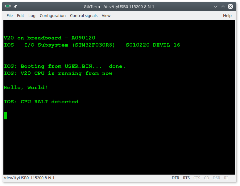
To make the firmware for the STM32F030R8 I've used Arduino IDE with the core made by ST. In this way the "porting" to the Atmega32 used in the final board would have been simpler.
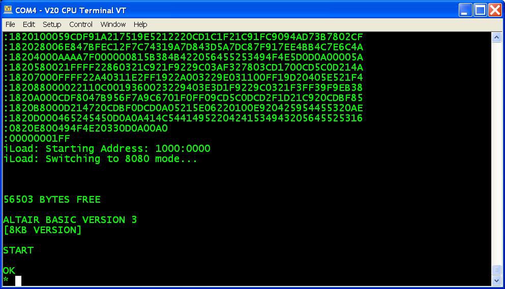
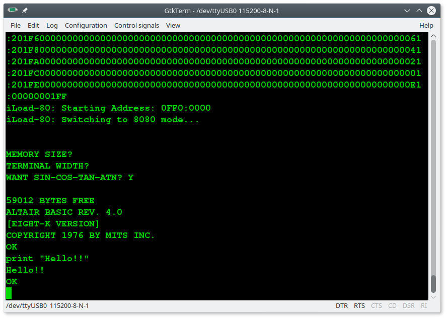
Here some screenshots of some tests using the 8080 mode to run the Altair Basic and the IMSAI Basic:

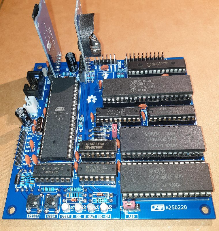
* * HARDWARE OVERVIEW * *
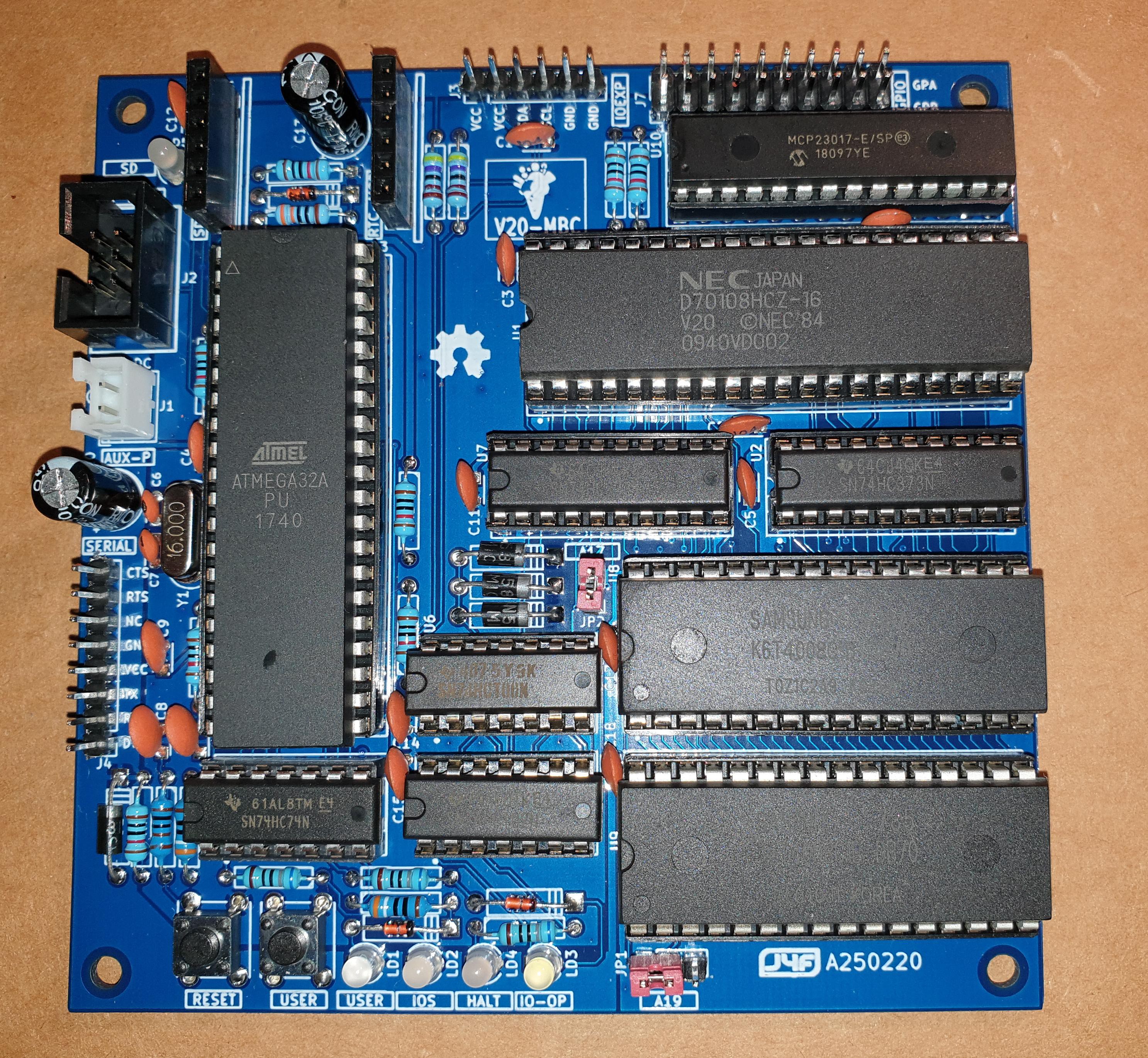
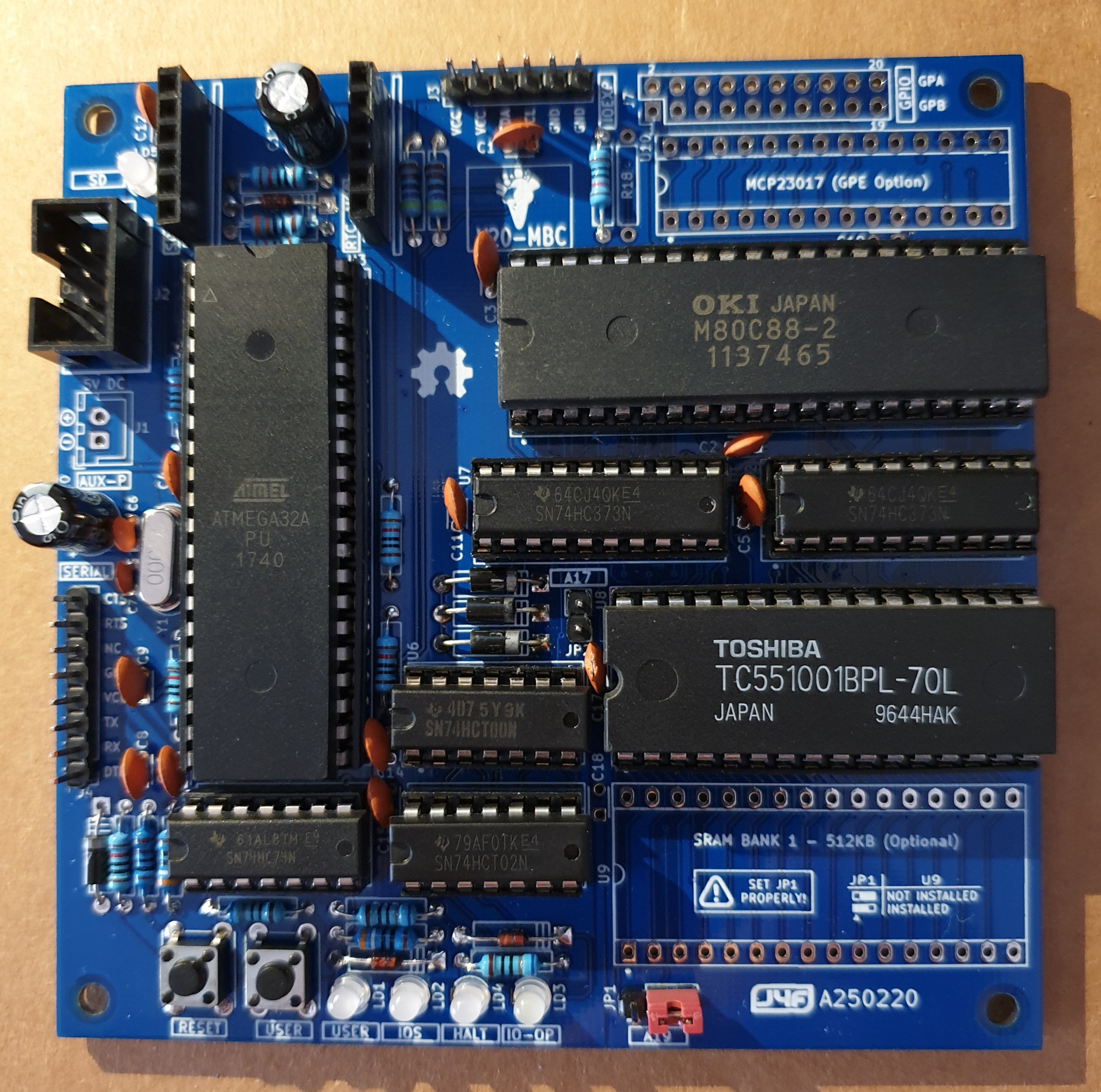
Here the V20-MBC hardware main specs:
- V20HL full static CMOS CPU (uPD70108H)
- can be used an 80C88 (CMOS version) too;
- RAM can be configured as 128/512/1024KB;
- optional RTC and microSD modules (the same used in the Z80-MBC2);
- optional 16x GPIO port;
- I2C expansion port;
- serial port;
- User led and key:
- ISP connector (for the Atmega32);
- clock can be configured at 4/8MHz (by software).
The CPU is used in "minimum mode" to limit the BOM.
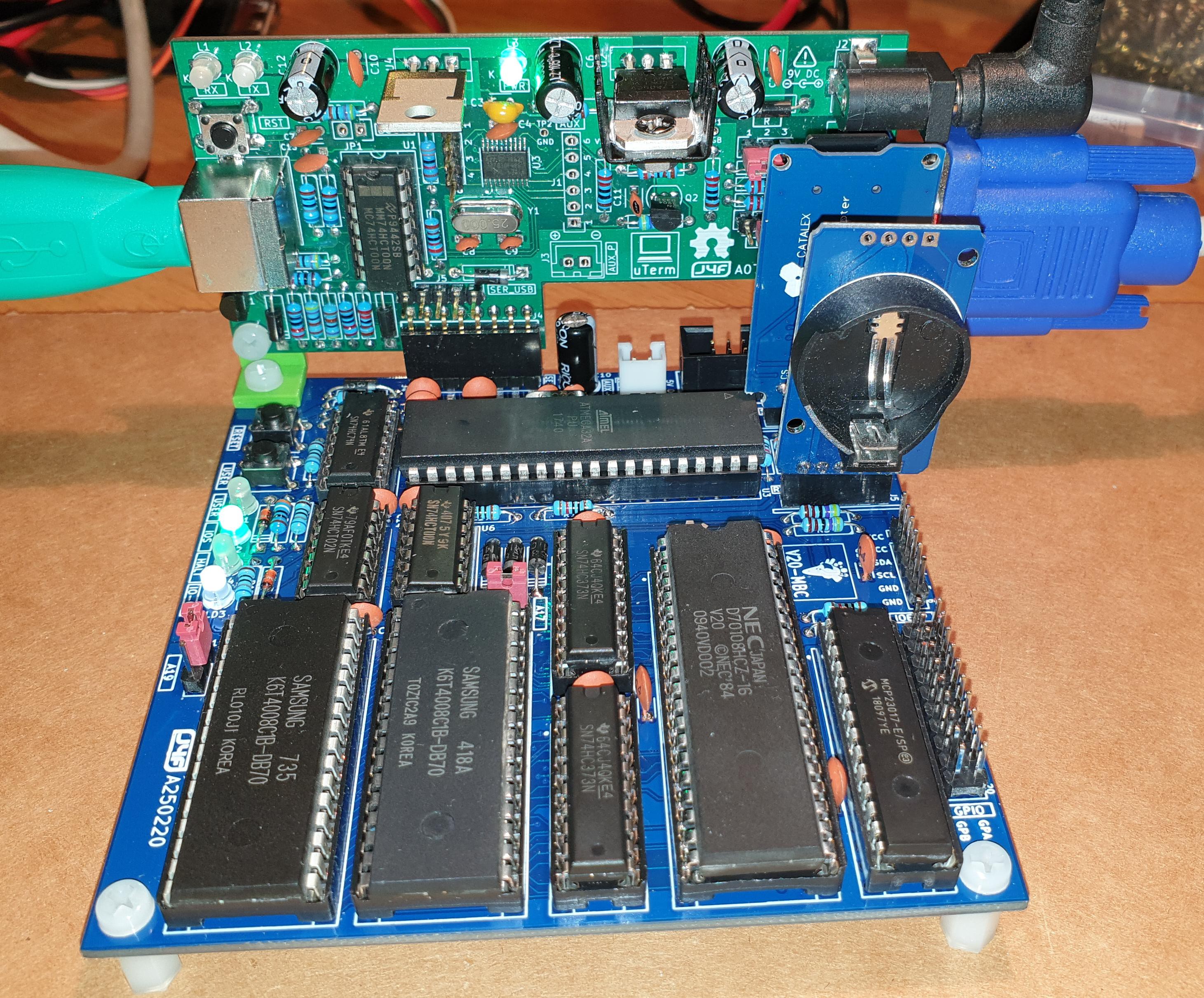
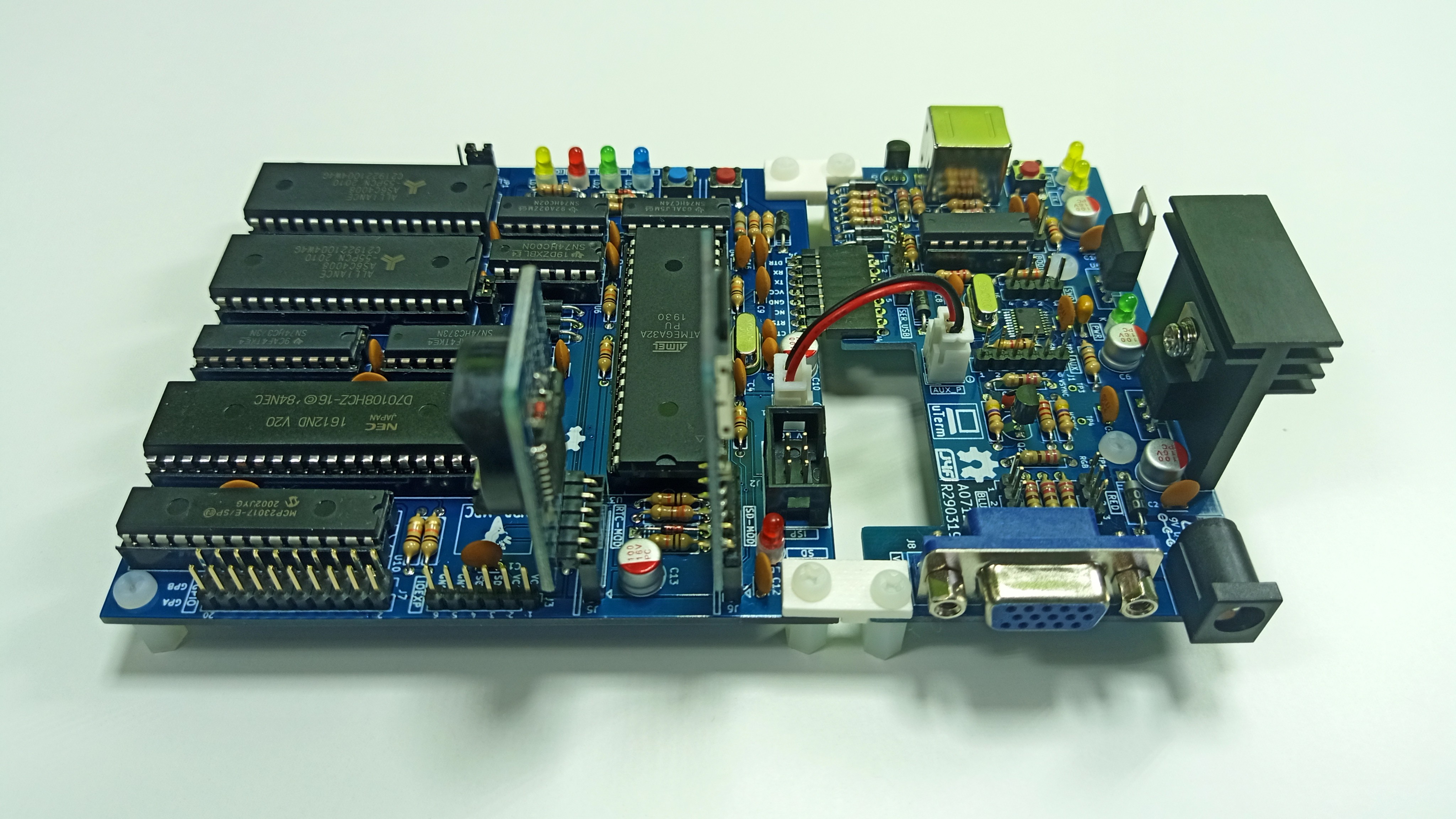
The layout allows to "plug in" a uTerm or a uCom board as in the Z80-MBC2 (vertically or horizontally) using the same 3D printed brackets (the following screenshot could change due to IOS updates).
The following images show a V20-MBC attached to a uTerm board to form an "autonomous" unit with a PS/2 keyboard and a VGA monitor (mounted vertically and horizontally):
Because it is a "two flavors" board (8088/8080), I've used a two flavors ice cream as logo... ☺
(the following screenshot could change due to IOS updates)
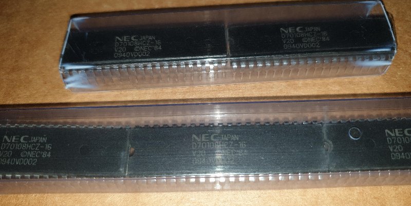
Please remember that a CMOS full static CPU is required here, so the only V20 CPU that can be used is the V20HL (uPD7108H, see the "H" at the end of the part code that makes the difference...).
Only this CMOS full static version allows to use a clock rate from DC and, under some conditions, guaranties that the logic levels are compatible with the Atmega32A ones (the Atmega logic input levels are not TTL compliant)
Another aspect of the V20-MBC is that the well known 8284 clock oscillator chip (normally used to generate the 8088/8086 clock with the required 33% duty cycle) is not used here. Reading the V20HL datasheet you can see that the -12 and -16 speed grades have a symmetrical clock requirement, and the -10 speed grade clock requirement can be met using a little lower clock with a 50% duty cycle (not greater than about 9MHz, so using a maximum 8MHz clock there is a good margin).
In the Files section you can find the V20HL Datasheet.
RAM CONFIGURATION
The V20-MBC allows three different RAM configurations:
- 128KB (1x128KB)
- 512KB (1x512KB)
- 1024KB (2x512KB)
To set the proper RAM configuration two jumpers (JP1/A19 and JP2/A17) must be set. This operation must be done when the board is not powered, and before the first power on with the RAM chips installed.
Please note that using a 128KB SRAM only the single SRAM chip configuration is supported (the 2x128KB is not supported).
The following table shows how to set jumpers JP1 and JP2 for the three RAM configurations:
CONSIDERATIONS USING AN 80C88 CPU
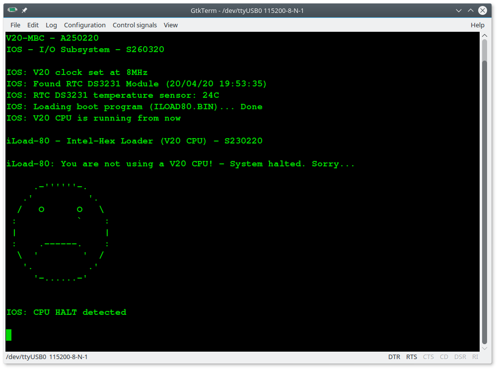
The V20-MBC can use an 80C88 CMOS CPU too.
Of course when using an 80C88 CPU you loose the 8080 mode specific of the V20HL CPU.
Please consider that when using an 80C88 a speed grade -2 is required (80C88-2) to meet the 80C88 specifications. If we see at the datasheet the clock requirements are:
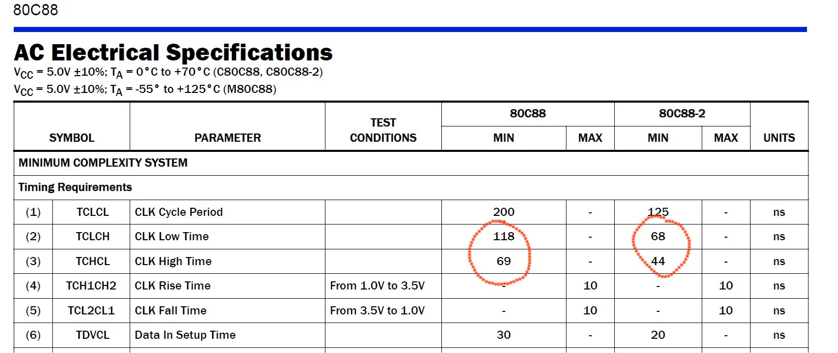
So a 8MHz clock with a 50% duty cycle will no meet both the 80C88 and 80C88-2 specifications, but a 4MHz clock with a 50% duty cycle will meet the 80C88-2 specs.
So you have to use an 80C88-2 CMOS CPU setting the clock at 4MHz.
Of course you can try to overclock "a little" the 80C88-2 CPU with a 8MHz clock, but doing so you are out of specs (anyway I've tried that without noticeable problems...).

And the following screenshot shows what you get if you try to execute an 8080 machine code having an 80C88 CPU (it could change due to IOS updates):
In the File section there is the 80C88 datasheet.
MINIMAL HW CONFIGURATION
It is possible set up a V20-MBC with a minimal HW configuration that allows "bare metal programming" as in following image:
The GPE (GPIO EXPANDER) option is not populated (U10, R18, C19, J7). More, the RAM is a 128KB chip and the Bank 1 (U9, C18) is not populated at all too.
In this example as CPU is used a 80C88-2, but of course you can use a uPD70108H (V20HL) too.
When this minimal HW configuration is used the only IOS boot option you can use is iLoad to load 8088 Intel-Hex executable files.
Anyway using iLoad you can load with a terminal emulator iLoad-80 as .hex stream (ILOAD80.HEX) to load and run 8080 executables with a two-steps manual loading procedure (see the SOFTWARE OVERVIEW section).
NOTES ABOUT THE COMPONENTS:
If it is more convenient for you, the 74HC logic ICs can be substituted with the 74HCT series.
The RAM chips speed grade used here is 70ns (e.g. TC551001-70 for the 128kB SRAM).
Please note that the USER led (LD1) * must * be blue or white or one with a V(forward) about >= 2.7V (otherwise the USER key may not work as expected).
NOTE on the uPD70108: some people reported a successful use of uPD70108C or uPD70108D CPU at 8MHz. Accordingly to the datasheet these aren't a full static design and have a minimum working clock, so in the boot phase they are out of spec here. Anyway if you have got one you can try...
THE SERIAL PORT
The SERIAL port (J4) can be connected to a TTL-RS232 adapter or with a serial-USB adapter like the one (CP2102 based) in the following image:
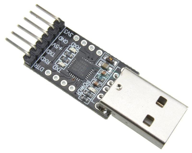
This serial-USB adapter can act also as power source for the V20-MBC, and has the DTR signal for the "autoreset" driven from the Arduino IDE to allow the upload of a "sketch" into the Atmega32A flash memory.
Note that the RTS and CTS pins of the SERIAL port (J4) are not currently supported and must be left disconnected (as the NC pin).
Also the 3V3 pin of the serial-USB adapter must be left disconnected:

NOTE on J4 pins names:
Please note that the SERIAL connector (J4) pins names are referred to the serial adapter, so the TX and RX signals are relative to the serial-USB adapter side (in other words TX and RX are already "inverted". See the schematic).
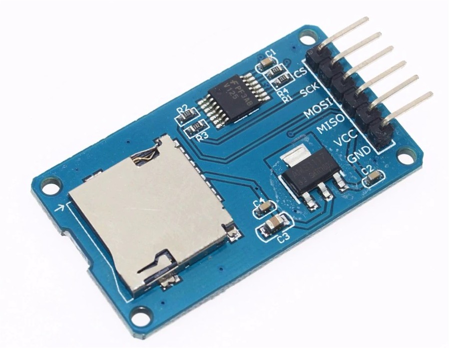
THE OPTIONAL SD MODULE
The optional SD module is used as HD emulation. The module is a common 6 pins microSD module that can be easily found on ebay:
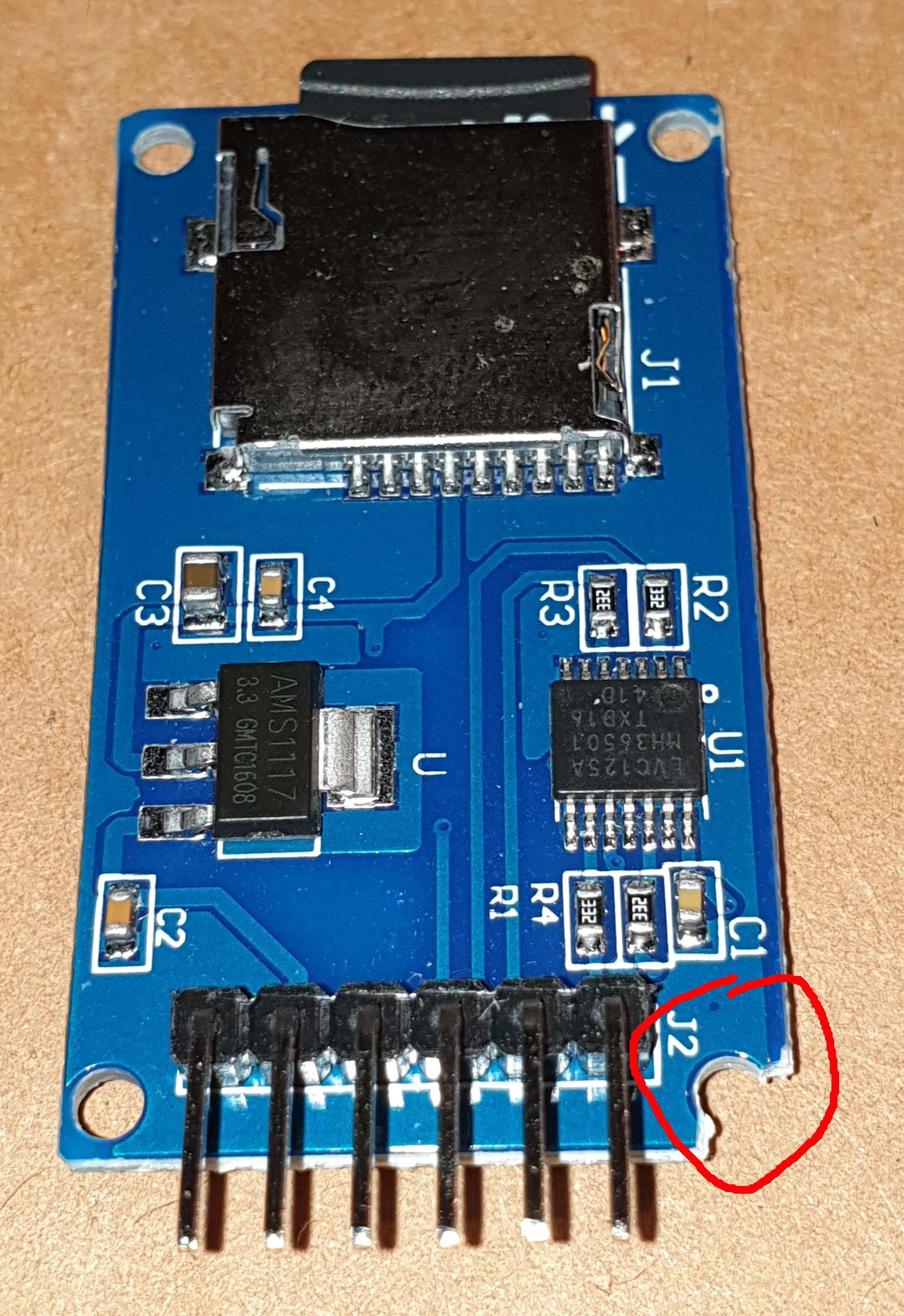
If a socket is used for the MCU Atmega32A, a little cut is required to allow a good insertion into the J6 connector.
The cut is in the right angle near the connector as shown in the following image:
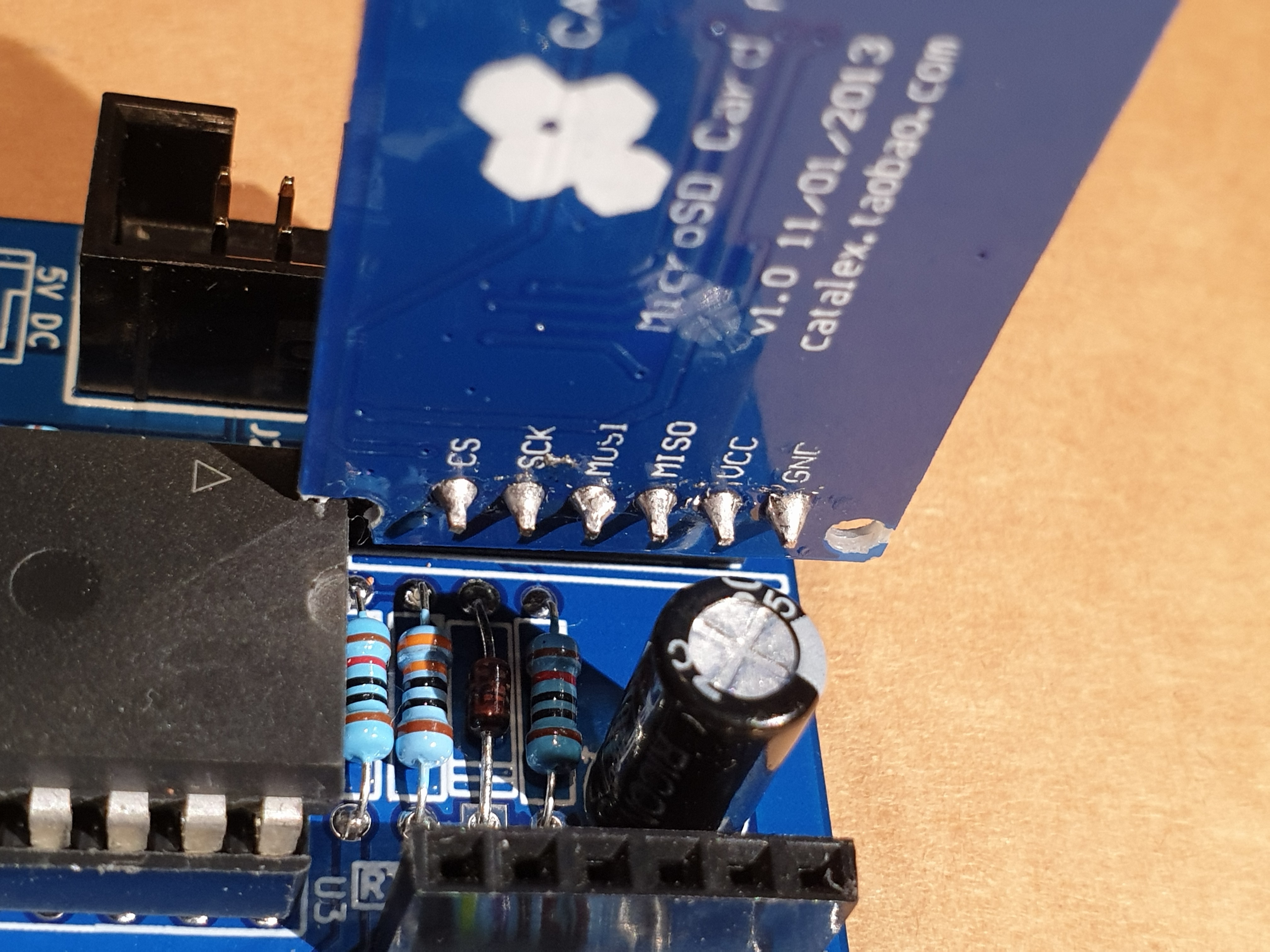
Pay attention on how and where you plug the module in (the only right connector for it is J6 marked as SD-MOD). If you plug it in the wrong connector or in the wrong way it is possible cause permanent damages to both the module and the V20-MBC board! So plug it as shown in the following image::
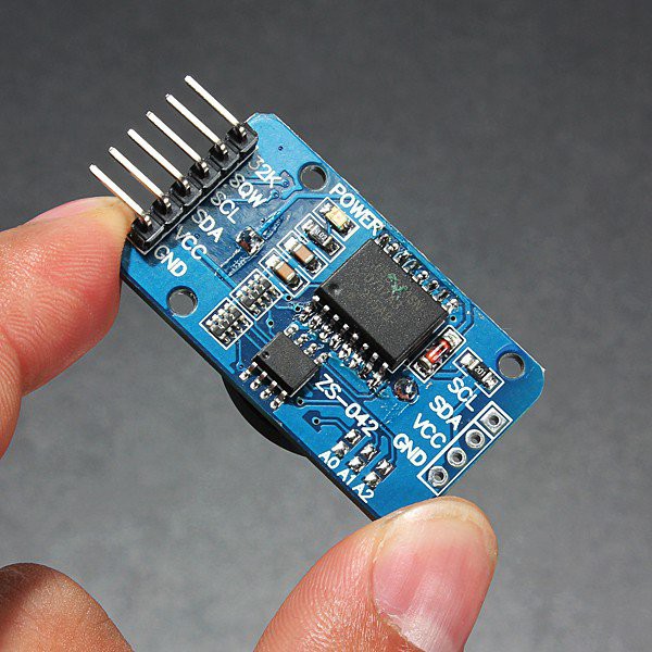
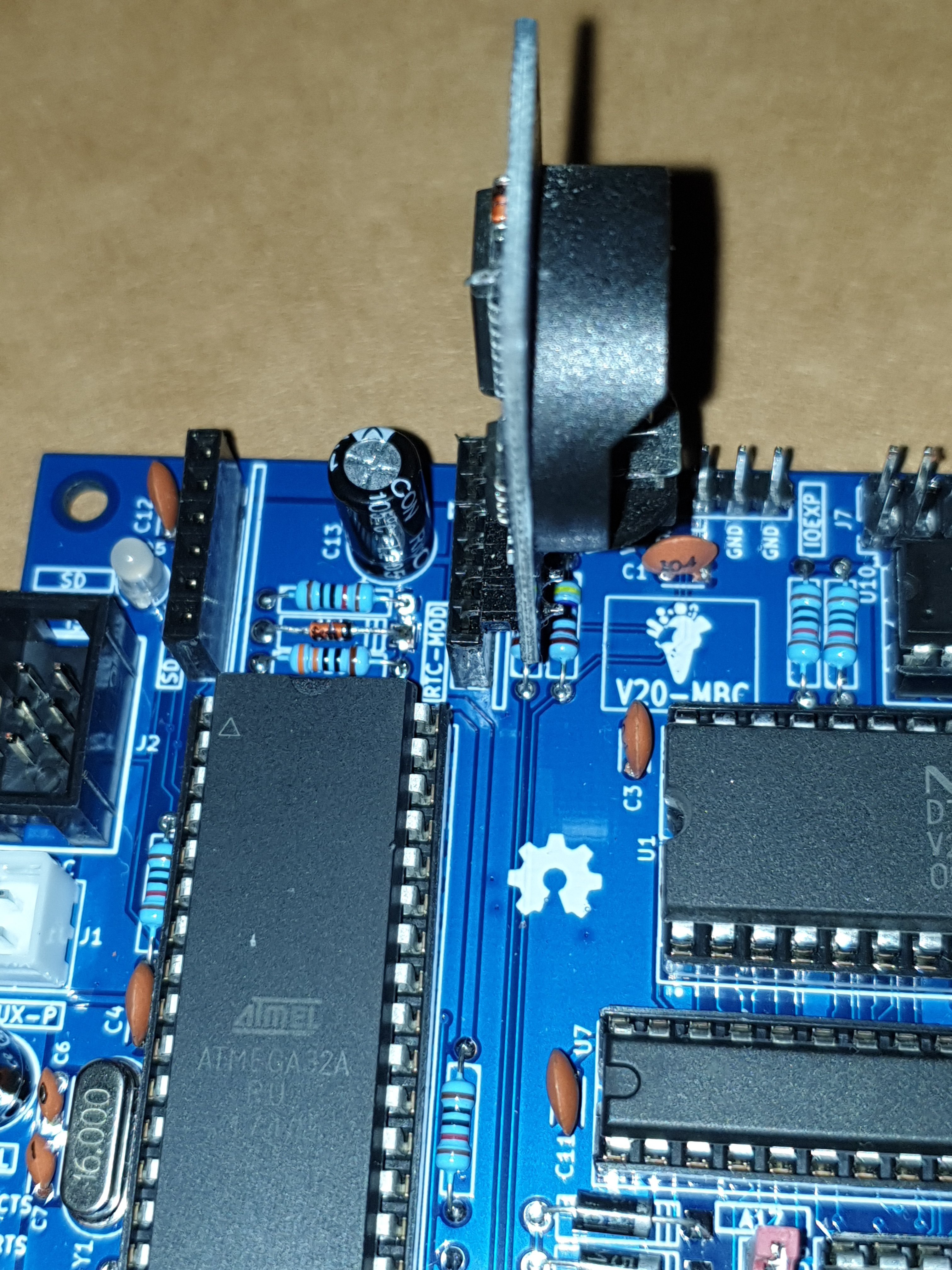
THE OPTIONAL RTC MODULE
The RTC is a common module based on a DS3231 RTC like this one:
This cheap modules have a trickle charging circuit that may cause the "explosion" of the battery if you use a standard CR2032 cell. More, it can damage also a rechargeable LIR2032 cell. For more information and how to fix it see here.
The RTC module has it's own pullup resistors on SDA and SCL. Because the value is 4k7 (the same value used inside the V20-MBC board), the resulting value will be:
4k7 // 4k7 = 2k3
Because this value is fine there is no need to take away the pullup on the RTC module.
Pay attention on how and where you plug the module in (the only right connector for it is J5 marked as RTC-MOD). If you plug it in the wrong connector or in the wrong way it is possible cause permanent damages to both the module and the V20-MBC board! So plug it as shown in the following image:
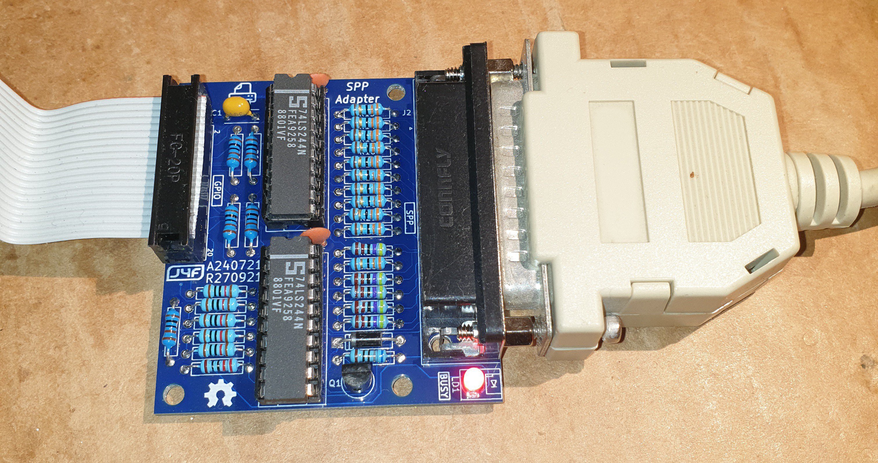
* * SPP (STANDARD PARALLEL PORT) ADAPTER BOARD * *
The Standard Parallel Port (SPP) Adapter board allows to use the GPIO port of the V20-MBC as a standard printer parallel port.
In this way you can use a legacy parallel (Centronics) printer.
To connect the SPP Adapter board to the GPIO connector of the V20-MBC board you need a 10cm long 20 wires flat cable terminated with an IDC connector at both sides (pay attention to connect the cable in the right way on both sides, so the pin 1 on the V20-MBC GPIO connector corresponds to the pin 1 on the SPP Adapter board GPIO connector).
Please note that you have to power off the V20-MBC board before connecting or disconnecting the SPP Adapter board to it.
NOTE: before using the SPP Adapter board (A240721-R270921, the same board used with the 68K-MBC) you have to update both the IOS firmware and the SD image to the latest available version (see the FILES section).
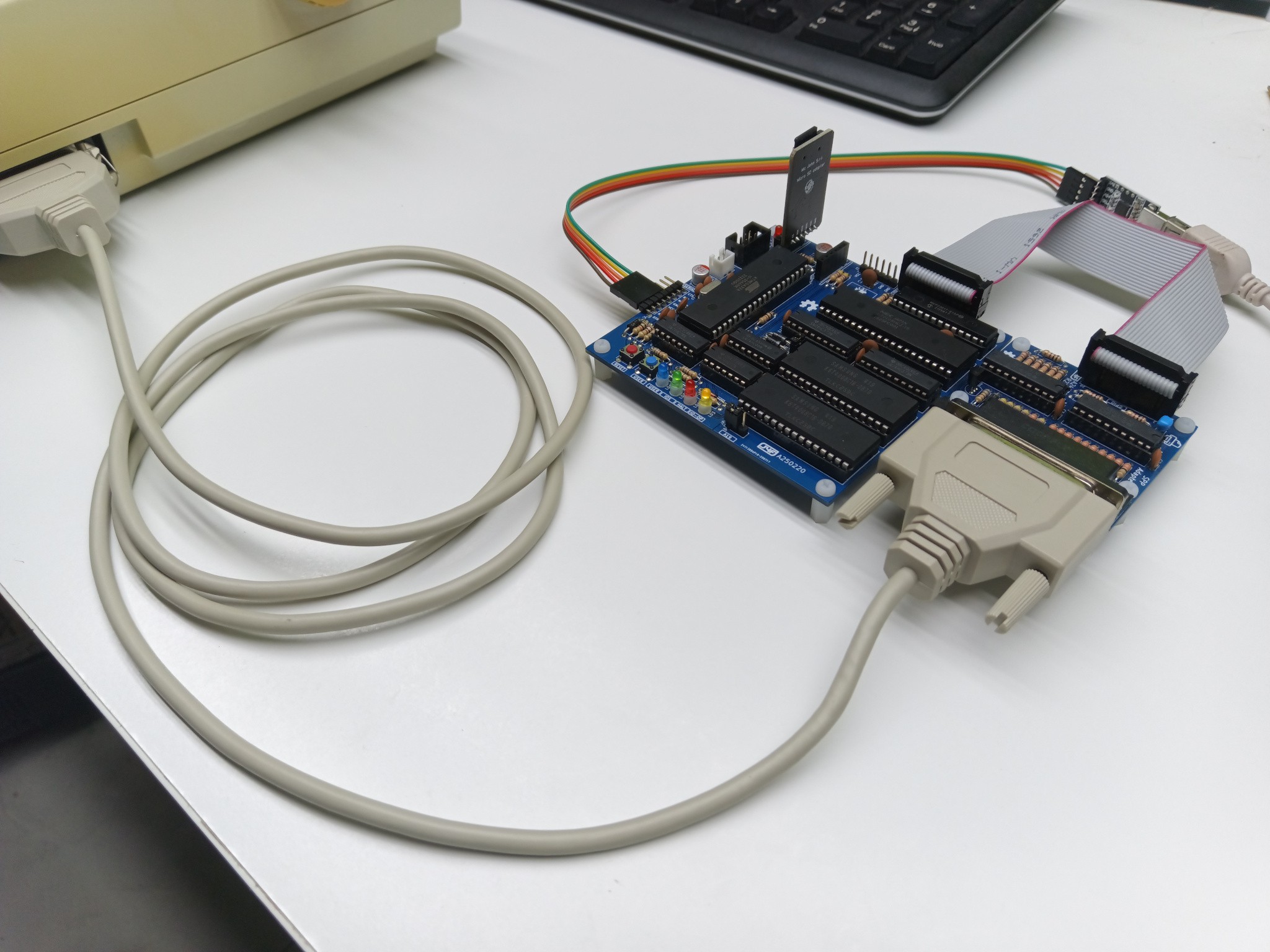
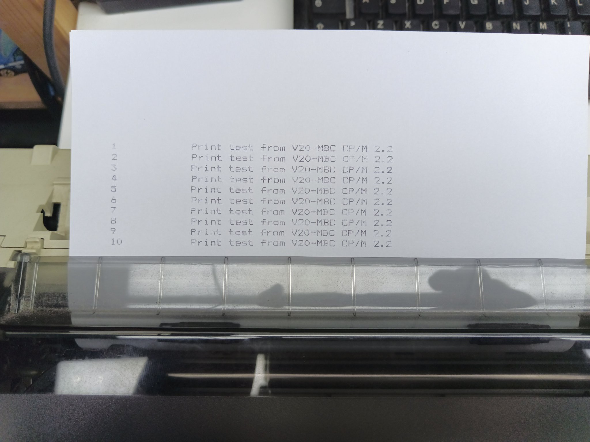
In the following image the SPP Adapter board with the flat cable (connected to the GPIO connector of the V20-MBC) and with the printer cable:
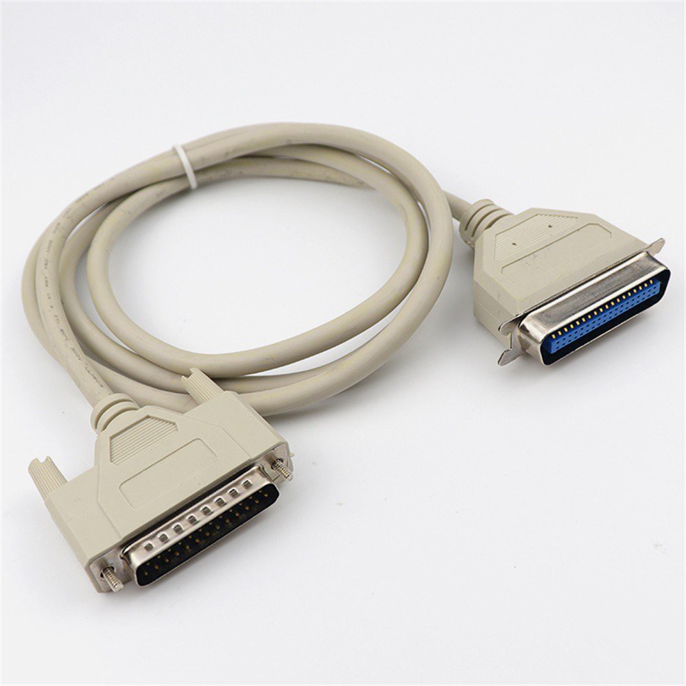
The cable to use for the printer is the common parallel printer cable, with a DB-25 connector at one side and a Centronics connector at the other:
Here a simple print test:
SPP: HOW TO BUILD IT
In the FILES section you can find a zip file with all the documentation needed to build the SPP Adapter board, including the Gerber files for the PCB production.
SPP: HOW TO USE THE SPP CP/M UTILITY
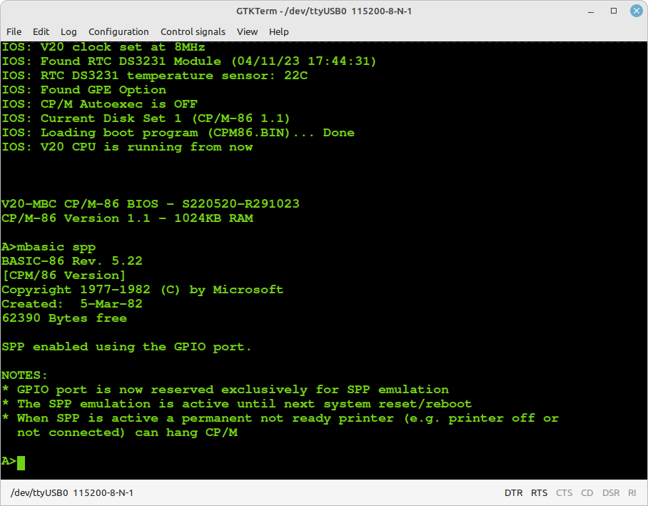
To enable the SPP Adapter board under CP/M 2.2 and CP/M-86 I've added on the drive A: the custom utility SPP.BAS.
You have to execute the SPP utility with the command MBASIC SPP to enable the SPP Adapter board and "link" to it the LPT: CP/M device inside CP/M. After the execution of the SPP utility the GPIO port will be linked and reserved (the "normal" GPIO opcodes/functions inside IOS will be disabled) to the SPP parallel port emulation until a system reset or reboot:
NOTE: the SPP Adapter board is currently supported under CP/M 2.2 and CP/M-86 only.
SPP: WHERE TO GET A PCB
I've prepared an "easy" link to get a small lot (5 pcs minimum) of PCB of the SPP Adapter. The link is this one.
SPP: HOW TO GET A KIT OR AN ASSEMBLED UNIT
If you are looking for a SPP Adapter board kit with all the needed parts or an assembled unit ready to use now there is a professional seller that can sell both and ship worldwide.
The link to the seller is this one.
* * SOFTWARE OVERVIEW * *
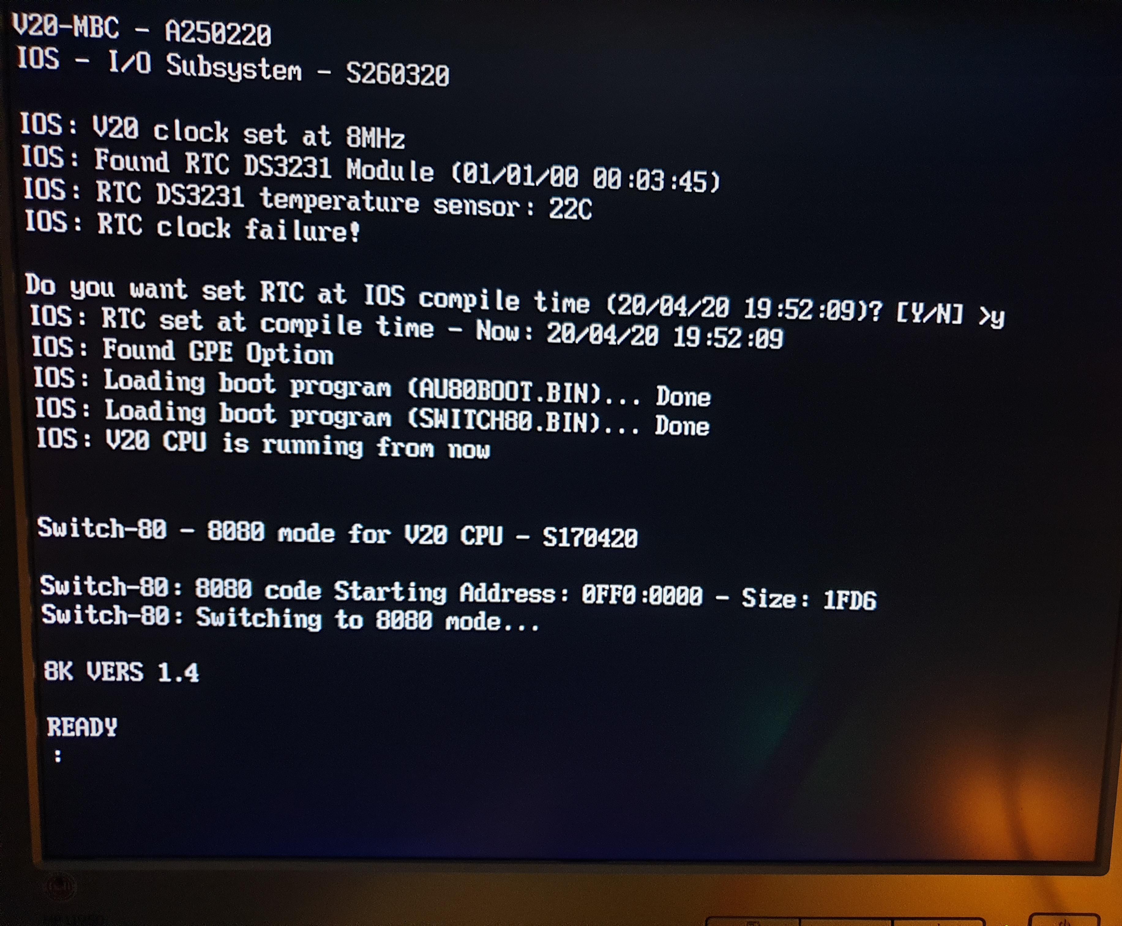
The MCU Atmega32A is used as universal I/O subsystem, as Eeprom, and as reset and 4/8MHz clock generator for the V20HL CPU.
The software running into the Atmega32A is the IOS (Input Output Subsystem) written using the Arduino IDE environment.
The IOS allows to interface the Atmega32A directly with the CPU system bus, emulating the needed I/O chips during the I/O read, I/O write and IRQ acknowledge CPU bus cycles (see the V20HL datasheet).
More, the IOS does the RAM load during the boot phase, "feeding" the CPU with the needed instructions to execute the RAM load.
If the "feeding" algorithm "sees" that there is a unexpected bus status, it aborts the boot sequence alerting with a message.
Because the V20HL CPU (as any 8088/8086 CPU) has an instructions prefetch queue, the IOS takes care of this in the "feeding" algorithm during the boot phase and appends at the end of each boot stage a HLT instruction to be sure that the CPU doesn't go further.
The boot stages can be one or two, depending on the kind of machine code. For 8080 machine code a two boot stage is used to load also the Switch-80 utility to support the switch to the 8080 mode of the V20HL CPU.
The parameters of the serial port emulated by the IOS are: 115200 baud, 8N1 (anyway you can change the parameters modifying the setting inside the .INO file as in any Arduino sketch) with no flow control.
If you prefer it, in the Files section there is also the IOS hex executable file ready to use with a programmer tool like the TL866. In this case remember to set the fuse bits as explained in the .hex file description (in the Files section).
FLASHING THE BOOTLOADER
Into the Atmega32A must be flashed an Arduino bootloader taken from here (Auduino IDE doesn't support the Atmega32A MCU "out of the box", so you must load an Atmega32 support library).
It is possible to use the Board Manager of the Arduino IDE to load the needed library to use Arduino IDE with the Atmega32A MCU (see here).
Flash the Arduino bootloader at first (with the method you prefer). An ISP (J2) connector is provided on the PCB to allow that easily.
You can find here a guide to flash the bootloader on Linux with the Arduino IDE "Burn Bootloader" option, using the USBasp programmer connected to the ISP port (it is the same method used for the Z80-MBC2).
Remember to disconnect any other connector when using the ISP port. Also the SD module (if present) must be removed from the board when the ISP port is in use.
THE SD IMAGE
The content of the microSD (I'll call it simply SD from now) is compressed into a zip file in the Files section.
When you update the IOS firmware you must always update the content of the SD too, as the SD image is normally suited for a given IOS revision.
You have to unzip it retaining the structure of the sub-directories into a FAT formatted SD card, so that the various root files (inside the .zip as the various .DSK files and so on...) are in the root of the SD itself.
IOS supports only FAT16 and FAT32. A 1GB SD is more than enough, anyway because they tends to be difficult to find now a 4GB SD can be a good choice.
About the SD technology, only "legacy" SD (aka SDSC with a capacity up to 2GB) and SDHC cards (2GB - 32GB) can be used. Other most recent types are not supported (so, no SDXC, SDUC,...).
What it really needed to let IOS run are only all the files in the root folder. The other sub-directories contain source files or examples or other kind of content (see next paragraphs).
Inside every sub-directory there is a README.TXT file that may contain important info/updates. Please read them all when you use a SD image first time or when update it!
In the root there is a ChangeLog.txt file with the changes log.
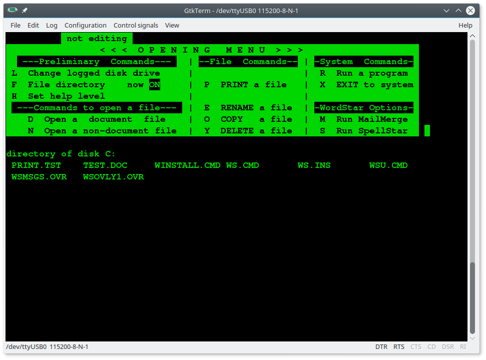
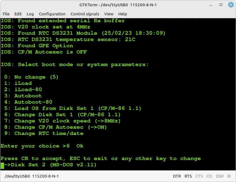
HOW ENTER IN THE "SELECT BOOT MODE OR SYSTEM PARAMETERS" MENU:
To enter in the "Select boot mode or system parameters" you must press the RESET key (SW1), release it and press immediately the USER key (SW2) and keep it pressed until the IOS led (LD2) starts to blink.
An other way is to press both keys, release the RESET key holding the USER key down until the IOS led starts to blink, or you see the menu on the screen.
Here a screenshot of the menu (it could change due to IOS updates):
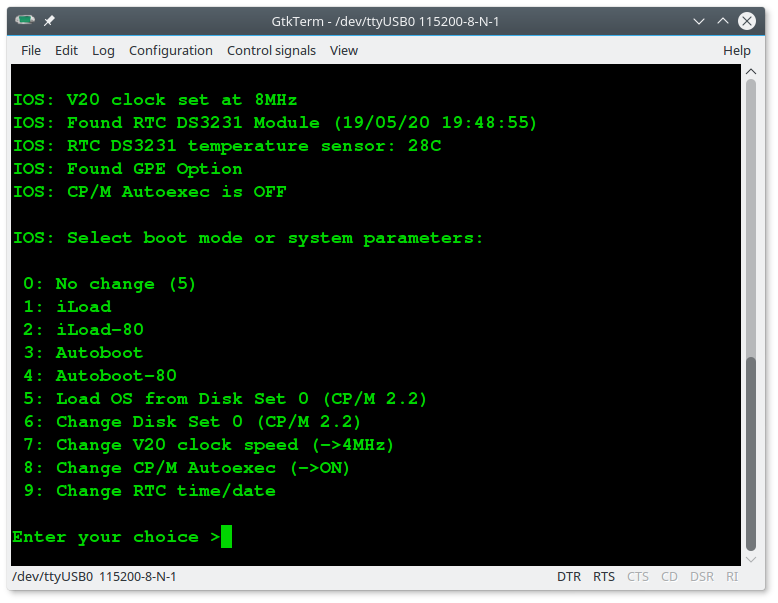
iLoad: loads and executes an 8088 Intel-Hex executable sent from the serial. It is the only loading utility embedded into the Atmega32 firmware, so it can be used in a minimal HW configuration without any optional SD or RTC module;
iLoad-80: loads and executes an 8080 Intel-Hex executable sent from the serial port;
Autoboot: loads and executes an 8088 binary file (AUTOBOOT.BIN) on SD;
Autoboot-80: loads and executes an 8080 binary file (AU80BOOT.BIN) on SD.
Load OS from Disk Set <n>: loads and runs an Operative System installed into the current Disk Set <n> on SD.
Change Disk Set <n>: Changes the current Disk Set to another one (only if it is supported more than one Disk Set). This command implements the Multiboot selection and it is used to switch among multiples OS.
Change CP/M Autoexec: Turns on or off the execution of the AUTOEXEC.SUB batch file at the cold boot. This is supported for CP/M 2.2 (8080 mode) and CP/M-86.
The remaining choices are self-explanatory.
On the current SD image the file AUTOBOOT.BIN is an HelloWord demo written in 8088 assembly (the source is in the \src folder on the SD), and the file AU80BOOT.BIN is the IMSAI Basic interpreter (adapted for the V20-MBC).
CP/M 2.2 (8080 mode)
This is the "classic" CP/M 2.2 (aka CP/M-80) for the 8 bit 8080 CPU.
Please remember that you are using here an 8080 execution mode, so only CP/M applications written using strictly 8080 machine code will run here!
CP/M 2.2 can run with any supported RAM configuration.

You have 16 8Mbytes disks from A: to P:. The disk A: is the "system" disk and it mainly contains the CP/M external commands, the XMODEM file transfer program, a couple of games (LADDER and CATCHUM), a couple of Basic interpreters (MBASIC and MBASIC85) and some basic programs (.BAS) as demo.
Other disks (from B: to P:) may contain some SW or be empty. For those containing SW I've added a file (README.TXT) with the name of the SW inside.
CP/M 2.2 WARM BOOT MESSAGE
Starting with IOS S260320-R241023 the message shown when CP/M 2.2 makes a warm boot is no more present.
If you are curious about how CP/M 2.2 handles this event it is possible to re-activate it easily.
I've added in the drive A: the utility SHOWWARM.BAS to enable the "warm boot" message.
To execute give the command: MBASIC SHOWWARM:
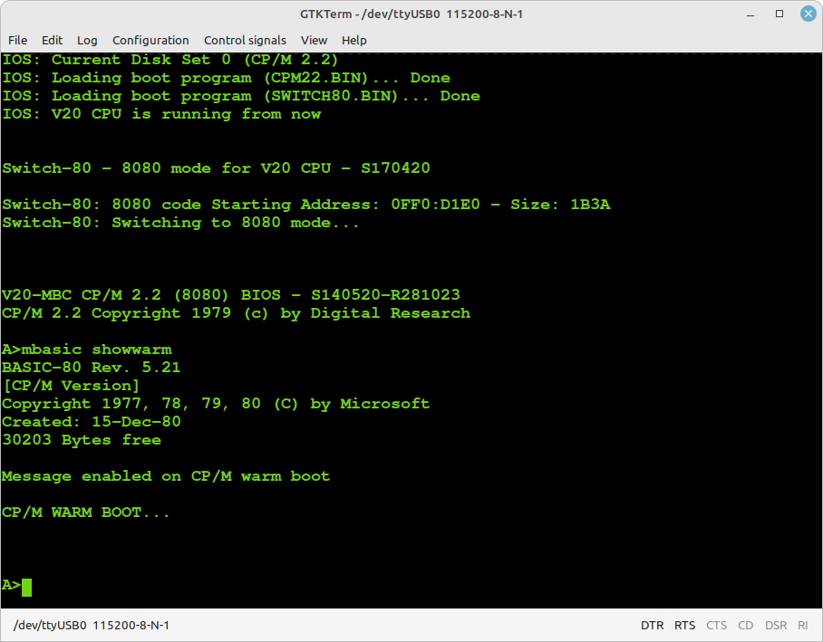
The message will be active until the next reboot.
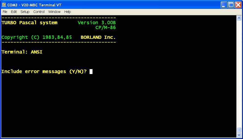
CP/M-86
This is the CP/M-86 v1.1 for the 8088/8086 CPU.
CP/M-86 can run with any supported RAM configuration. I added in the custom Bios a routine to size the installed RAM (128/512/1024KB) and adapt the TPA (Transient Program Area, the user programs space) size accordingly. The detected amount of RAM is printed in the sign-on message:

You have 16 8Mbytes disks from A: to P:. The disk A: is the "system" disk and it mainly contains the CP/M external commands, the Microsoft Basic interpreter for CP/M-86 (MBASIC.CMD), the DRI Personal Basic interpreter (BASIC.CMD) and some basic programs (.BAS) as demo.
Before using the DRI Personal Basic it is highly recommended to read the Tutorial/Manual in the Files section.
Other disks (from B: to P:) may contain some SW or be empty. For those containing SW I've added a file (README.TXT) with the name of the SW inside.
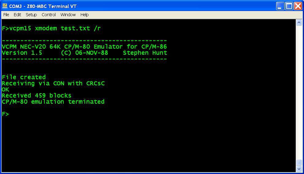
EMULATING CP/M-80 UNDER CP/M-86
In the CP/M-86 Disk Set I've added in the disk F: an interesting CP/M-80 emulator under CP/M-86: VCPM15.CMD.
It can emulates a complete CP/M-80 environment using the 8080 mode of the V20 CPU. Of course it can run only if a V20 CPU is used.
The level of CP/M-80 emulation is so good that you can run XMODEM for CP/M-80 with no problem.
To run a CP/M-80 application (.COM) just give this command:
VCPM15 <CP/M-80_application>
where <CP/M-80_application> is any CP/M-80 executable file (.COM).
Some examples:
To receive a file with xmodem: vcpm15 xmodem test.txt /r
To send a file with xmodem: vcpm15 xmodem test.txt /s
To run startrek: vcpm15 mbasic85 startrek
To run catchum: vcpm15 catchum
To run ladder: vcpm15 ladder
As a curiosity I've also added a pure software CP/M-80 emulator: 8080.CMD.
This is a CP/M-80 and 8080 CPU emulator all in software, so it can run on a 8088 CPU too.
Of course it is a lot slower than the previous one because the 8080 CPU emulation is all done by software, and it has some limitation on the degree of CP/M-80 environment emulation too (e.g. XMODEM can't run).
For more info read the README.TXT file located in the drive F:.
CP/M-86 WITH AUTO-SWITCH TO CP/M-80
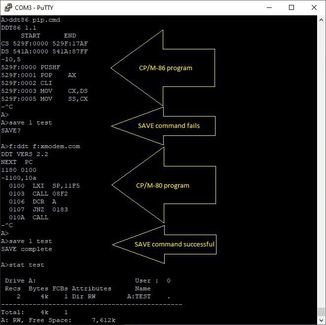
Thanks to Stephen Hunt, the author of the VCPM15 utlity, it is now possible to automatically execute either CP/M-86 or CP/M-80 programs without the need of the VCPM emulator program that he wrote back in the 80s. If the program is a .CMD it will be executed as normal, and if it is a .COM it will be loaded into an 8080 environment and then executed. The modifications that he has done into the BIOS also adds a SAVE command that allows saving pages from the 8080 memory bank. The SAVE command is only available following execution of an 8080 program and only if the 8080 memory bank is still available:
The modified BIOS source code (and the compiled ready to use cpm86.bin binary file which can be copied into the SD card) can be found here:
https://github.com/binaryspider/v20-mbc_cpm8680_cbios
Thanks Steven!
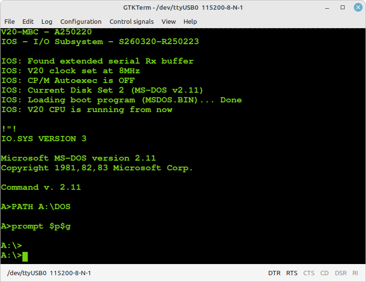
MS-DOS v2.11
Thanks to Kevin Price now MS-DOS v2.11 is running on the V20-MBC!
To try it you have to update both the IOS and the SD content to the latest version (see the Files section) and select it from the "Select boot mode or system parameters" menu:
Of course there isn't any video card in the V20-MBC, so only the programs that don't access directly to the video RAM can run here.
Please note that you need 512KB or 1024KB RAM installed to run it. Four drives (A:, B:, C: and D:) are supported:
More info about how to add files into the virtual disks are on the Kevin Price repo on github: https://github.com/keyvin/v20mbc-msdos.
NOTE: Do not use the CPMTOOLGUI utility (see next paragraph) to add/delete files inside the virtual disks used for MS-DOS, but follow the method described on the Kevin github link above!
HOW ADD FILES INSIDE A CP/M VIRTUAL DISK USING CPMTOOLSGUI
The V20-MBC maps any disk like A: B: C: etc. into an image file on SD card with this file name: DSxNyy.DSK;
where x (from 0 to 9) is the Disk Set containing an OS:
0 = CP/M 2.2
1 = CP/M-86
2 = MSDOS (do not use CPMTOOLSGUI for them!)
and yy (from 00 to 15) is the disk (00 = A: 01 = B: etc.).
You can download CpmtoolsGUI (English Windows version) from here.
Extract the file CpmtoolsGUI.exe in a new folder and add/overwrite the file diskdefs copying it from the cpmtools folder inside the SD.
-> STEP 1
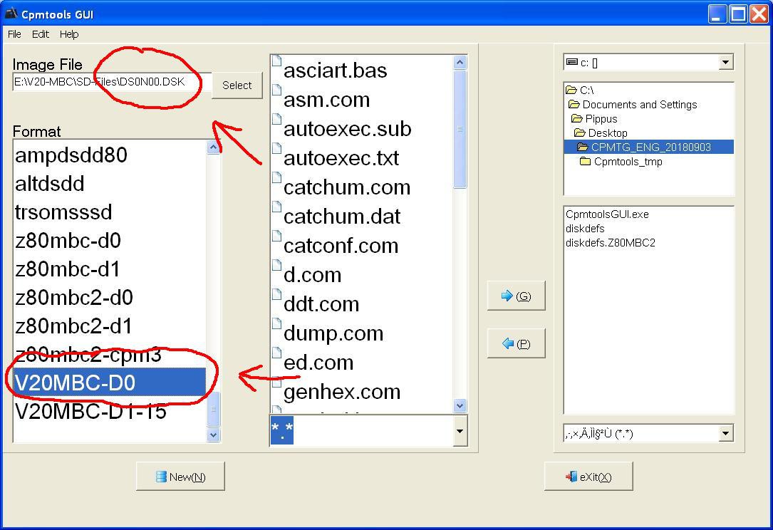
Select in the upper left window (Image File) of the CpmtoolsGUI tool the virtual disk where you want to add files.
For CP/M 2.2 and CP/M-86: select "V20MBC-D0" only for disk 0 or "V20MBC-D1-15" for the other disks (disk 1 - 15) in the bottom left window (Format) of CpmtoolsGUI.
In the following image is selected (Image File) the disk DS0N00.DSK that corresponds to the disk A: (yy = disk = 00 = A:) of the CP/M 2.2 OS (x = 0):
-> STEP 2
To add one or more files to the selected virtual disk you have simply point the upper right selection window to the folder where the new files are stored in your PC, select them using the bottom right selection window and press the "<- P" button. After the add you'll see the added file names in the center window (together with the other files previously present).
-> STEP 3
Exit from the the CpmtoolsGUI tool pressing the eXit button.
To extract one or more files from a virtual disk the procedure is the same, just press the "-> G" button instead.
To delete a file inside the virtual disk, select it in the central window, press the right mouse button and select Delete (you can't overwrite a file in the virtual disk, but you have to delete it first).
NOTE: use cpmtoolsGUI only to add, extract or delete files inside a virtual disk. Not try to create new virtual disks files with cpmtools or cpmtoolsGUI because further processing is required for a valid virtual disk file.
HOW ENABLE THE EXTENDED RX BUFFER FOR XMODEM
Because the V20-MBC uses a virtual serial port without handshaking there is a timing problem when dealing with the 128 bytes packets used by the XMODEM protocol.
So the support to the XMODEM protocol has requested changes to extend the serial port RX buffer to 128 bytes.
Thanks to user Hans who pointed me to the right direction, there is a simple way to modify the size of the RX buffer used for the serial port.
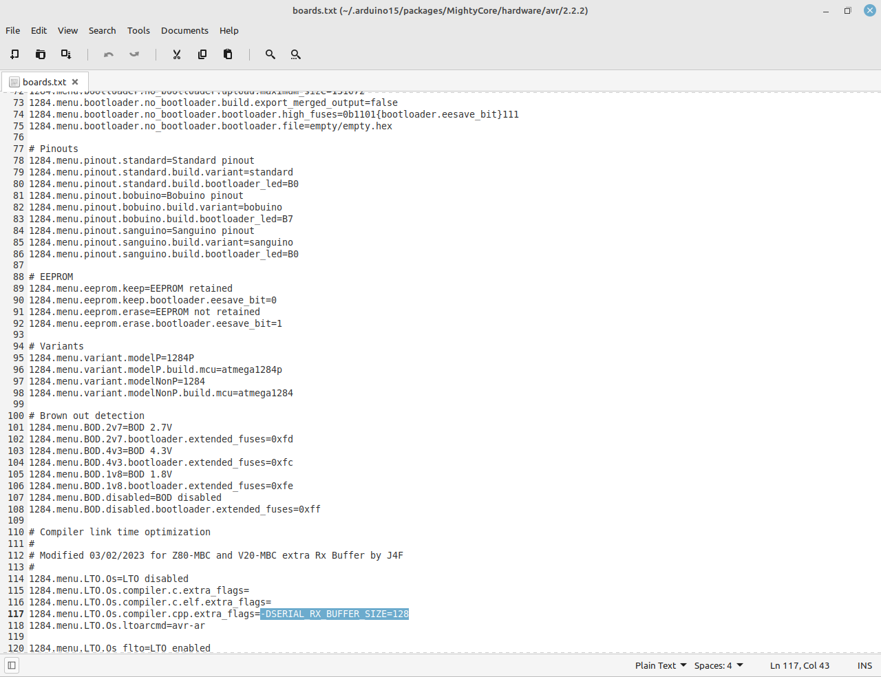
Search the file boards.txt related with the MightyCore variant in your Arduino IDE.
In a typical Linux Arduino IDE installation it is located in the hidden directory:
/home/<username>/.arduino15/packages/MightyCore/hardware/avr/2.0.5/
or in a Windows 10 installation:
C:\Users\<username>\AppData\Local\Arduino15\packages\MightyCore\hardware\avr\2.0.5
Open board.txt with an editor and locate the section related to the Atmega32/A:
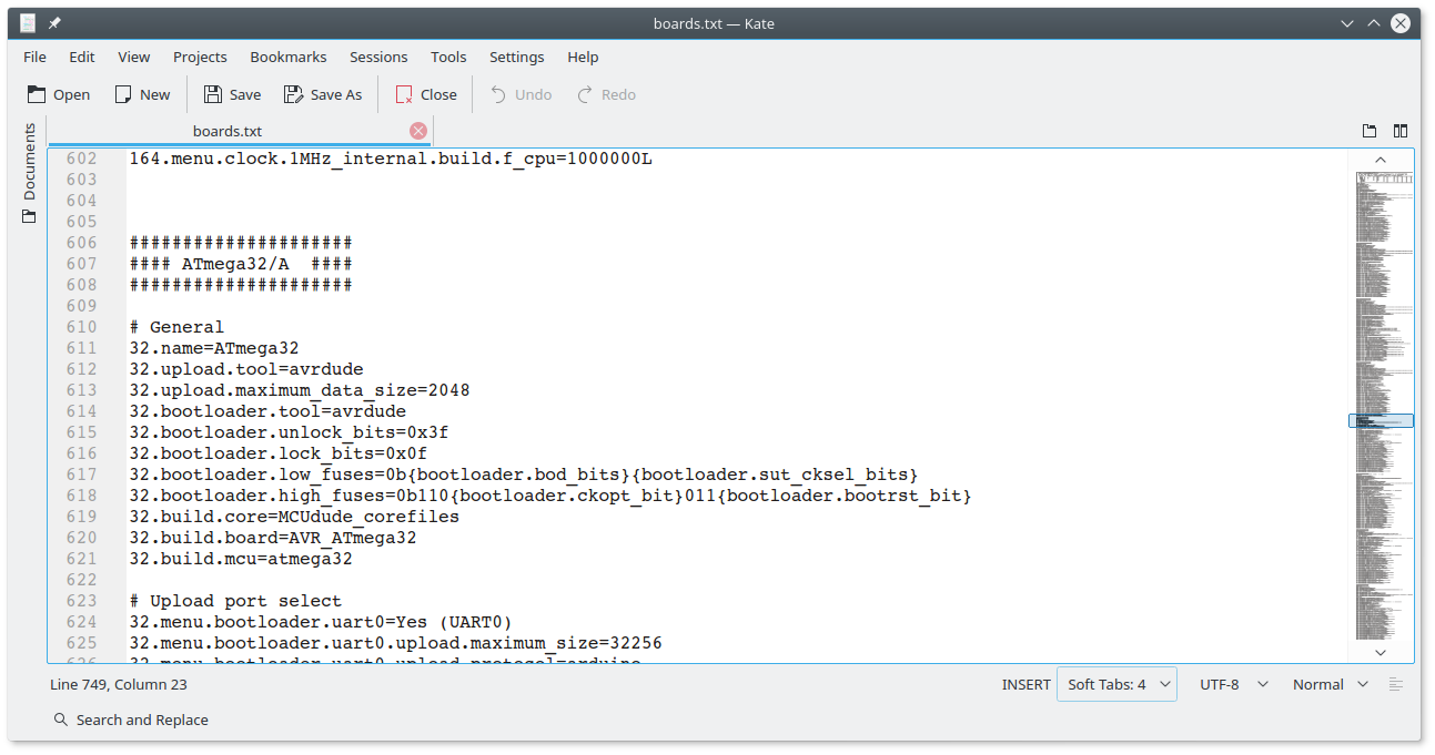
go some lines down until you see the "32.menu.LTO.Os.compiler.cpp.extra_flags=" line:
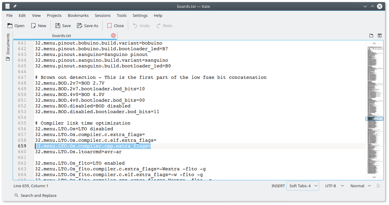 then append the string "-DSERIAL_RX_BUFFER_SIZE=128" to that line:
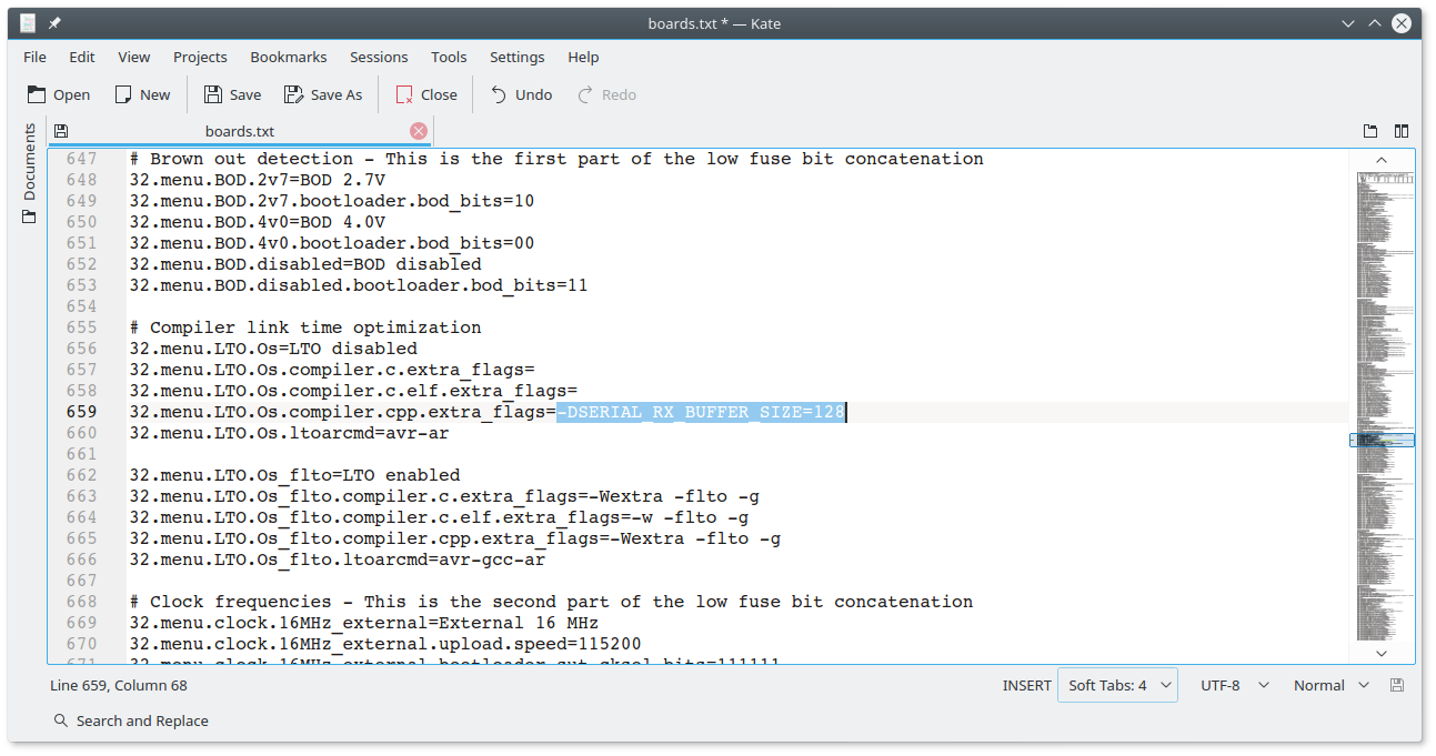
Save the edited board.txt file.
All done!
At this point you can recompile with the LTO option disabled and flash the IOS inside the Atmega32A with the extended RX buffer enabled.
Please remember that if you update the MightyCore you will lose the changes. In this case re-apply the previous steps.
Note that IOS checks if this extended buffer is active, and in this case will print a status line during the boot phase ("IOS: Found extended serial Rx buffer").
HOW TO USE ILOAD
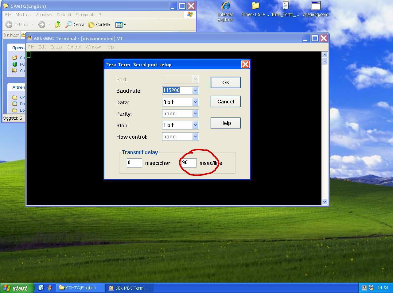
When using iLoad to load an executable program in Intel-Hex format from the serial port, remember to set a 50/90ms delay on every transmitted line into the serial port setting of the SW terminal you are using.
In the following image there is the setting window for TeraTerm:
This is required because the standard serial port of the Arduino firmware doesn't use any handshaking control.
ILOAD: HOW SETUP AN 8088 CROSS-ASSEMBLER AUTOMATED TOOLCHAIN (WINDOWS)
Using the iLoad boot mode it is possible setup an automated toolchain to cross-assemble, load and execute on the target (the V20-MBC) an 8088 assembler source program without physically touch the board (like a "modern" development board) , running a single batch file (AL.BAT) from the Windows command-line shell.
Remember that iLoad uses an Intel-Hex format that can only manage a 64KB address space (it uses 16 bit for the address and it doesn't manage segments), so the program must be conform to a "tiny memory model" where both code and data share the same 64KB segment (of course you can use other segments for not initialized data, but all the code generated must have the addresses inside a unique 64KB segment for the above limitation).
During the loading phase iLoad takes the first address of the Intel-Hex stream as the starting address of the program, and after the loading phase it jumps to it (so you have to be careful when you write your program startup).
To setup an automated toolchain under Windows you have to install Tera Term and the NASM x86 assembler at first.
You have to use an USB-serial adapter with the DTR signal as the one described in the HW section, and the driver must be already installed and "linked" to a COMx: port (the DTR signal is used to reset the board from the workstation and start an iLoad load&execute session).
In the \teraterm folder inside the SD image zip file there are the needed files and the detailed instructions in the README.TXT file (remember to modify both the AL.BAT and LoadV20.ttl files according to your installation, as explained in the README.TXT file).
I've used this toolchain under Windows 10 and in a Windows XP VM too.
Here a video using the HelloWord.asm source file example (in the \src directory inside the SD image, but you can try the "S230220 iLoad-80.asm" source file too):
Before to start writing your first program it is probably a good idea to give a look at the "S200220 iLoad.asm" source file (in the \src directory) and read the details about the memory allocation in the comments at the beginning of the file.
Please note that Tera Term resets the V20-MBC when the macro (LoadV20.ttl) is called from AL.BAT. This explains the need of the DTR signal on the USB-serial adapter (it uses the same "trick" to upload an Arduino sketch).
You have to close the Tera Term window to terminate the execution of the AL.BAT batch (before a new run).
THE \8080 FOLDER (SD IMAGE)
In this folder (inside the SD image) there are some applications written in 8080 assembler.
To assemble you must use the TASM assembler (see notes at the beginning of each .asm source file).
Here there are also the compiled binaries in .bin and .hex format ready to be used.
The .bin are the 8080 executable binary files. To use a 8080 .bin file with the V20-MBC you must use the Autoboot-80 option to load and execute an 8080 binary file.
Copy the wanted .bin file in the root of the SD and rename it as AU80BOOT.BIN.
Then from the "Boot mode and System parameter" menu of IOS choose option 4 (Autoboot-80) to run the renamed .bin file.
Another way is to use iLoad-80 (Intel-Hex loader for 8080 executables): from the "Boot mode and System parameter" menu of IOS choose option 2 (iLoad-80) and load the wanted .hex file using a terminal emulator.
If you don't have the optional SD module, you can run these executables anyway using the .hex format (Intel-Hex) with a two-steps manual boot:
1) First from the "Boot mode and System parameter" menu of IOS choose option 1 to activate the iLoad Intel-Hex loader, then load the ILOAD80.HEX file.
2) At this point you have a running iLoad-80 (Intel-Hex loader for 8080 executables) and you can load the wanted .hex file using a terminal emulator.
Remember to set the terminal emulator to add a 90ms delay for each line sent (see the terminal emulator manual about how activate it).
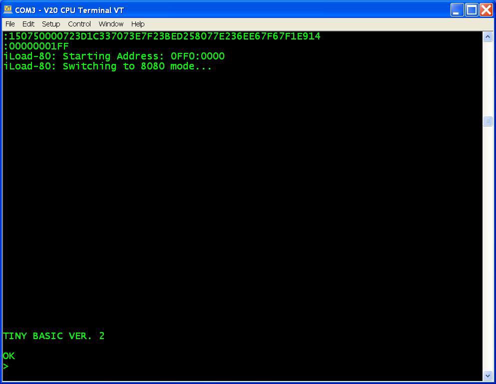
As default in the provided SD image the AU80BOOT.BIN file in the SD root is the IMSAI Basic.
In the \basic_demo folder there are some examples for the IMSAI basic.
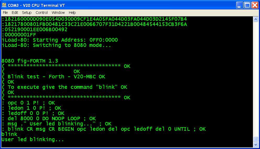
In the \forth_demo there is the example for fig-FORTH.
Please remember that the IMSAI Basic and the Tiny Basic accept only uppercase commands!
More when using IMSAI Basic remember to give a NEW command at first before doing anything else!
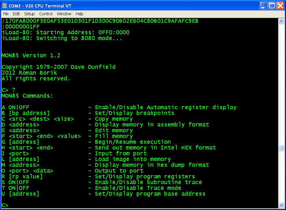
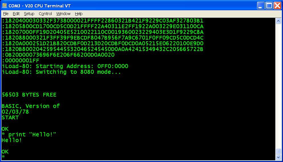
In the following images there are some screenshots of the various 8080 applications in the \8080 folder:

* * USING AN ATMEGA1284/ATMEGA1284P * *
Starting with IOS S260320-R241023 it is possible to use an Atmega1284/Atmega1284P as MCU. This will leave more space for any customization.
Of course you have to re-compile the IOS source selecting the right MCU.
Remember to apply the changes described in the paragraph "HOW ENABLE THE EXTENDED RX BUFFER FOR XMODEM (CP/M)" searching for the Atmega1284 section:
* * WHERE TO GET A PCB * *
I've prepared an "easy" link to get a small lot (5 pcs minimum) of PCB. The link is this one.
* * HOW TO GET A KIT OR AN ASSEMBLED UNIT * *
If you are looking for a kit with all the needed parts or an assembled unit ready to use now there is a professional seller that can sell both and ship worldwide.
The link to the seller is this one.
* * V20-MBC USERS GROUP * *
An "Users Group" was created on Facebook (it is the same used for the Z80-MBC2): https://www.facebook.com/groups/388307645238660/
* * LICENSING AND CREDITS * *
All the project files (SW & HW) are licensed under GPL v3.
If you use this material in any way a reference to the author (me ☻) will be appreciated.
CP/M seems to be Open Source now (see here).
PetitFS was developed by ChaN.
Forth stand-alone interpreter was originally ported to the Z80-MBC by Bill Westfield.
The CP/M-86 with auto-swtch to CP/M-80 is an implementation by Stephen Hunt (the same author of the VCPM15 utility).
MS-DOS v2.11 was ported by Kevin Price.