 Phil Malone
In Log #7 I showed my first attempt at pairing the hoverboard with the Jenx Stander.
It was OK, but not optimal. I really wanted to find a method that still used the Caster mounts, but one that provided a better turning radius, was very robust, and did not require major mods to the hoverboard itself. This meant I had to disassemble the hoverboard and really look at it's internal structure. I wanted to find a way to design an external mounting plate that could be attached to the hoverboard using existing mounting holes, surfaces etc.
The HOVER-1 ULTRA uses a very strong cast aluminum frame with plastic clamshell covers to shield the electronics. (See this gallery pic). What was interesting is that there are opening in the aluminum underneath the electronics to allow the "foot detect" switch actuators pass through. These are beam-break sensors on the bottom of the PCB that are actuated by rubber mounted pressure plates on the outside of the hoverboard. After completely disassembling the hoverboard I could investigate my options.`
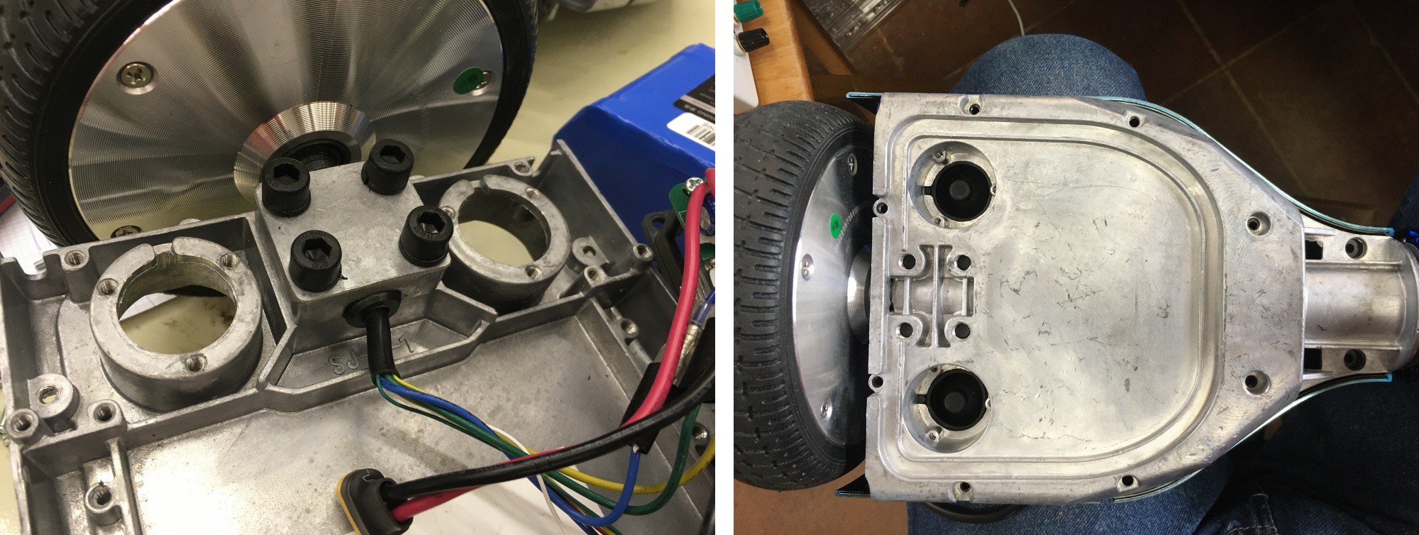
The underside is on the left, and the topside is on the right.
The one thing I was most concerned with, when designing the mounting method, was keeping the attach-point as close as possible to the wheels. The further away these two points were, the greater the buckling force would be on the board and the mounting plate. Greater forces mean heavier plates and bigger bolts etc.
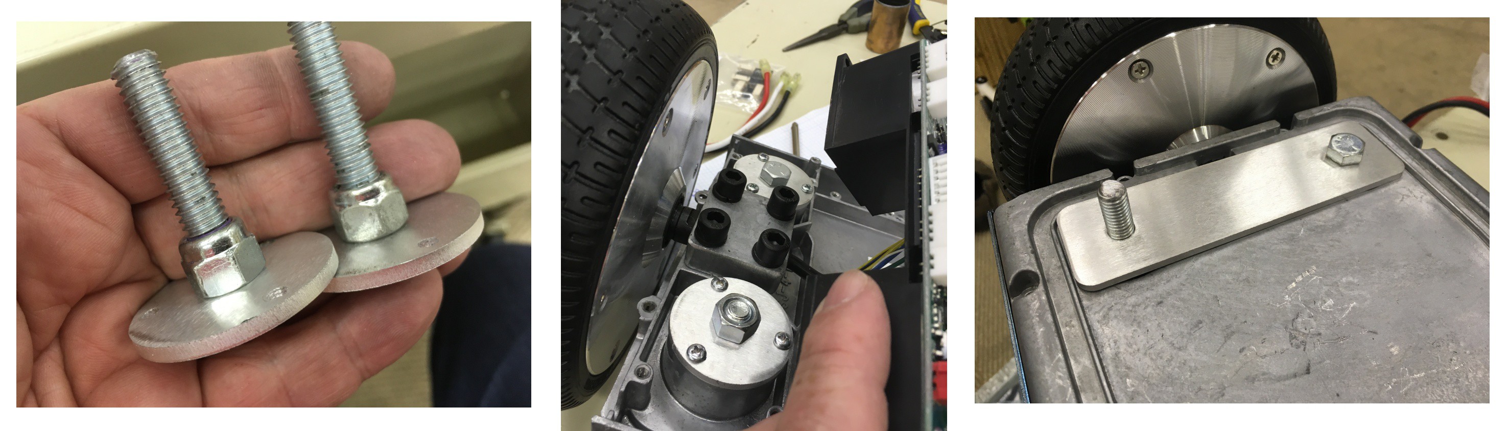
In the end I think I came up with a clever solution. I would form a hoverboard "sandwich" by placing a small aluminum plate on either side of the board, and tie them together with bolts that went through the large openings. I would use an oversized bolt, which would also form the mounting point. The "bread" plates on the underside of the board would actually be small disks that bolted to the chassis using the holes that were used to hold the rubber beam breakers in place. On the topside I would use a single plate, with two matching holes, that fit snugly inside a depression in the casting.
Each side of the hoverboard only really needed one mounting point, so the other bolt was just used to firmly anchor the top plate in place, and help spread the load. The bolt that is going to be a mounting point is attached to it's disk with a locknut, so once it's screwed in place it won't move. The other shorter bolt was inserted through the top plate and just attached to the mounted disk with a nut.
Note: My plan is to change this method by adding captive rivet nuts to the disks so all the bolts are just inserted from the top once everything is assembled.
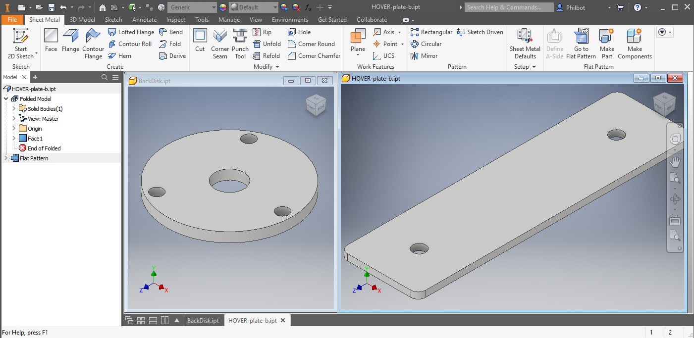
I made my first prototypes by hand, but getting the hole spacing and location correct was a pain. Since I knew I would need more I did a quick CAD design and order a few sets from sendcutsend.com You should never discount the time it takes to make a part, and the benefit gained from paying a service to fab it accurately for you.
Since the resulting bolt spacing did not match the caster wheel spacing, I had to remove the connecting pivot bar from between the two hoverboard halves. This was actually the most difficult mechanical part of the project, because the ring-clips used to hold the bar in place was a PAIN to get off. I then mounted the two halves to the frame to see how strong everything was. Since the caster mounting holes were inside 1" steel tubes, when everything was bolted together, the resulting structure was immensely strong. With the 3/8" bolt snugged (not cranked) down there was absolutely no wobble or deflection when I placed a load on the Stander.

The only issue was that I could rotate the hoverboard due to it's single point of attachment. So I decided I just needed to replace the central pivot tube with something else to keep the two sides aligned. This posed a bit of a problem since I had needed to separate the two sides by about 4 inches, and the existing tube was too short. I came up with a temporary solution which will work for now, but I have ordered a longer piece of stainless steel tube that will provide alignment, and additional strength if someone decides to stand on the hoverboard to take a ride.
The other issues was that the power cable that spanned the two sides was now short, so I spliced an additional 4" of wire inline with the existing cable. An alternate way to do this would be to create a short power jumper cable, but I didn't have any of the battery connectors.
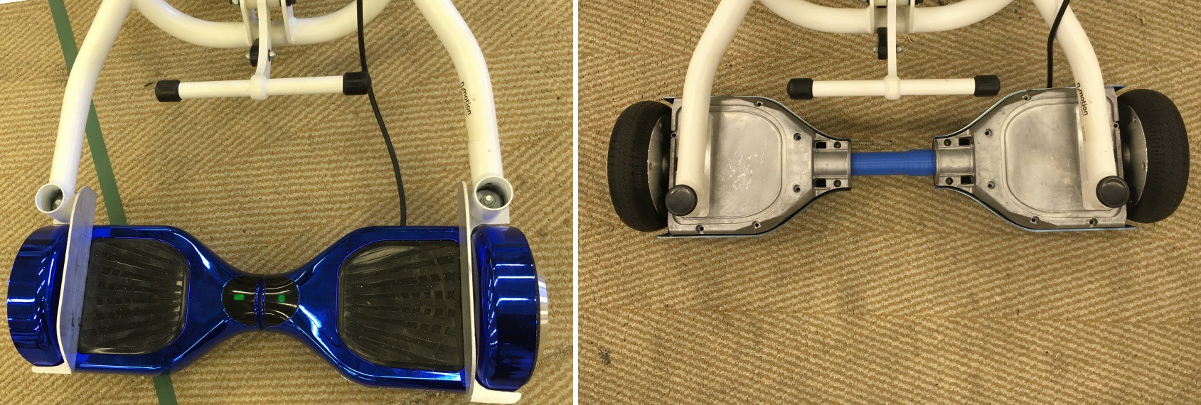
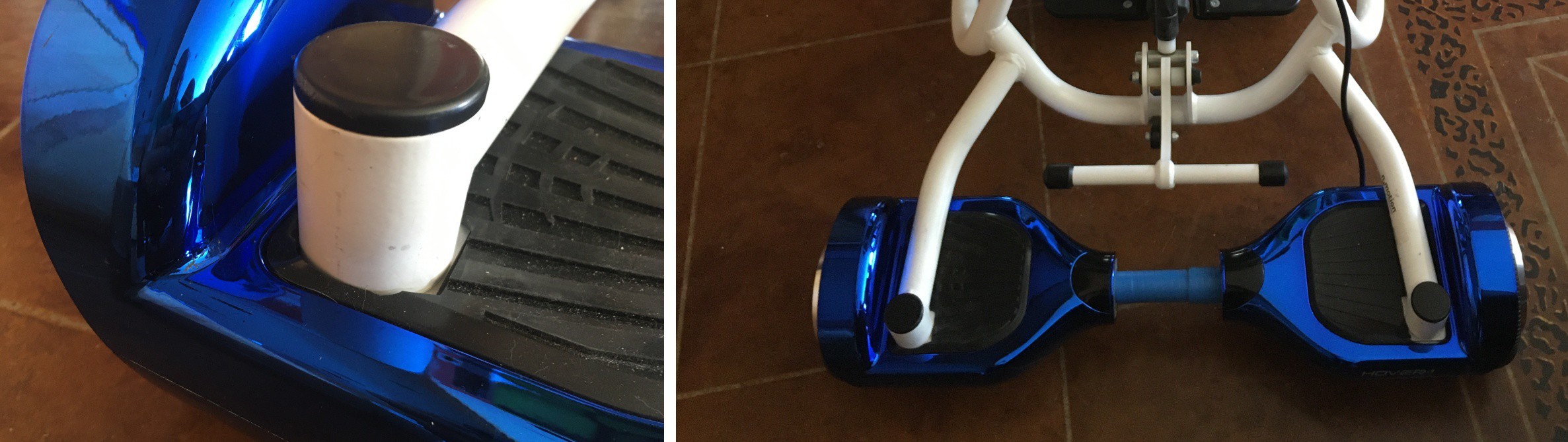
I thought it would be fun to compare the two mounting configurations. The pic below shows how much shorter the new configuration is. Couple this with the slightly larger wheelbase and the turning circle & speed control is a big improvement.
I did some unloaded tests and thinks look pretty good so far.
To complete the design, I made some cutouts in the rubber foot pads to allow the Stander frame to keep a solid contact with the aluminum plate, and re-assembled the clamshell. I think it looks pretty cool.
Discussions
Become a Hackaday.io Member
Create an account to leave a comment. Already have an account? Log In.