 Phil Malone
My first attempt at adding a wireless remote controller to the Hoverboard wasn't really successful (see Log #5). Using the ESP32 controller's WiFI capabilities increased the current demand by enough to overload the Hover-Board's 5V regulator.
So, for my drive testing, I just switched to a wired joystick.
However, after some live testing, I really wanted to try wirless again, so I started researching some lower power alternatives. I ran though a whole range of analog and digital "garage door remote control" style chip sets, but I really couldn't find any I was happy with.
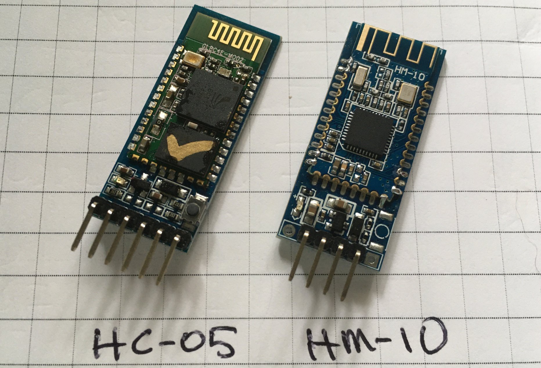
Then I started researching various Bluetooth serial link modules. I started with the HC-05 which is a master/slave device that can be used to establish an automatic connection between two serial ports. This was pretty easy to setup, but it seemed a bit dated. The next version I discovered was the HM-10 which is newer, and uses less power.
To create a Joystick that could be used with either of these devices, I'd need to put some sort of microcontroller in the Joystick, and then have it talk to a serial port on the Hoverboard. The Hover-Board motor controllers have several serial ports onboard, but I'd been trying to ONLY use the ones that were normally used for Master/Slave communications. This had required me to add a Micro-Controller inside the Hover-Board case, and have it plug into each of the motor controller boards. In this way, both controllers were acting as "SLAVES".
After much soul searching, I decided to abandon this approach, and use one of the "debug" serial ports on the Master Motor Controller. This mean that I could go back to using a single flipped cable to connect between the Master and Slave controllers. My HUGS protocol was still compatible with passing commands between the two controllers, and I could ALSO use it to pass commands from the Joystick to the Master controller.
This new approach has some key benefits:
1) I could remove most of the extra wiring I had added to the Hover-Board. This would make it easier for other hackers to replicate my setup.
2) The only electronics that needed to be added to the Hover-Board was an HC-05 Bluetooth module which could be connected directly to the REMOTE port on the Master Motor Controller board. This reduced the 5V power load to only 8mA
The downsides to this approach were:
1) I had to solder a set of header pins to the Master Motor Controller board. This was easy enough for me, but it does require some decent tools and some reasonable skill. I had been trying to avoid anyone else having to mod the controller boards because they use high voltage and current, so bad soldering can be disastrous.
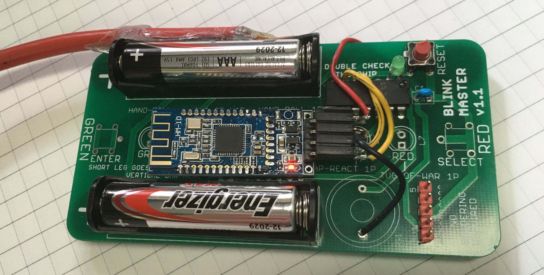
2) The joystick also now needs a HC-05 module, PIC (or other) processor and a battery that needs to be managed to get a reasonable run life. I did some testing with a Blink-Master board I had on hand. It gave me a convenient way to try out some PIC code with the HM-10 carrier board.
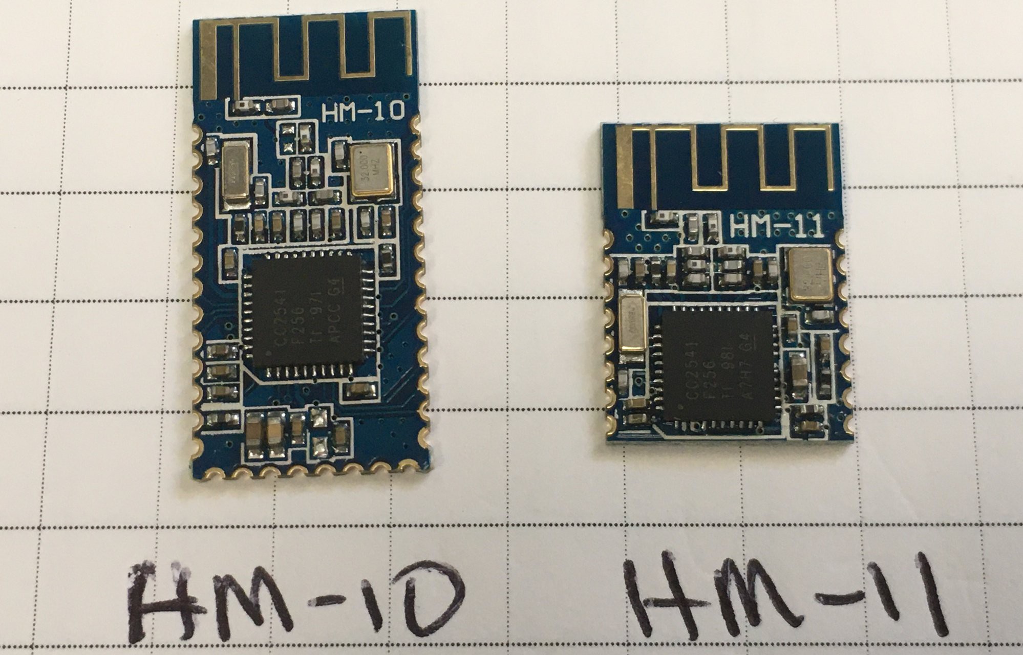
My plan is now to produce a custom PCB that can be used for the Joystick, with a snap-off segment that forms a smaller PCB to be used inside the Hover-Board. Instead of using the full sized module on it's carrier, I'll probably just use the minimal surface-mount module. Here is the HM-10 and it's little brother, the HM-11. Note: Those are 1/4" grid squares they are sitting on.
I'll open-source the PIC software and protocol so anyone can create their own joystick/controller using a pic, arduino or other smart controller. You could even use a Raspberry PI, and do image processing for a visual controller.
Discussions
Become a Hackaday.io Member
Create an account to leave a comment. Already have an account? Log In.