 Phil Malone
In Log #10 I experimented with Bluetooth modules to see if I could make a low cost wireless Joystick controller for my hacked hoverboards. My early success led me to design a custom PCB that could satisfy several requirements:
1) The board must be able to interface to either a micro-switch, or potentiometer based Joystick.
2) It must be able to generate smooth (trapezoid profile) velocity commands .
3) It must provide a fool-proof Bluetooth interface from the joystick to the hoverboard.
4) It must run on batteries, but have a long operational life (> 50 hours) and standby time (> 30 days).
My first prototype is shown below.
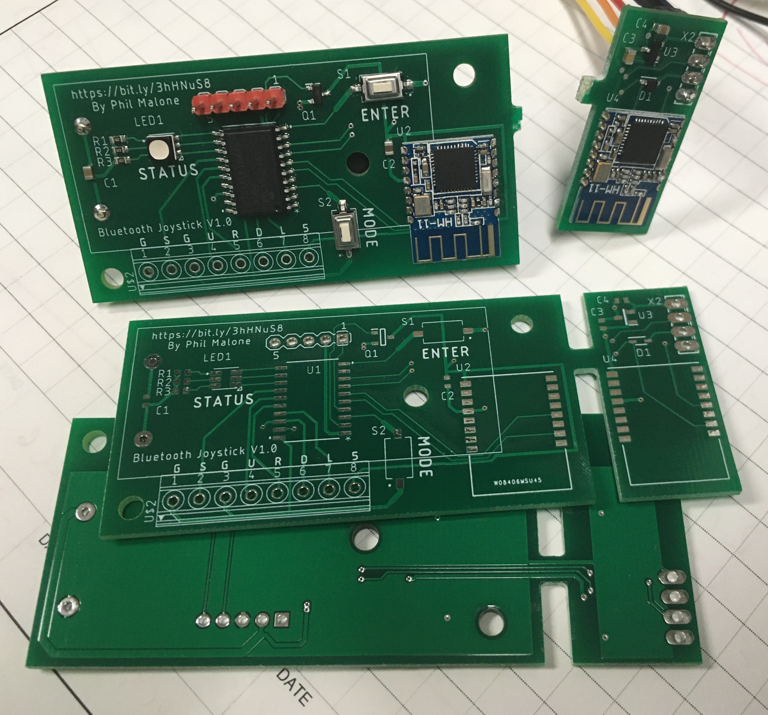
It may not be immediately obvious, but the board is pretty small. It's just 1 1/4" x 3 1/4".
What you may find interesting, are the two slots on the board. These are designed to enable me to snap the board into two pieces (see the top of the photo). The piece on the left is the Joystick interface and Bluetooth (BT) module. The piece on the right is the matching bluetooth (BT) module that will plug onto the header strip on the hoverboard motor controller. You also can't tell from the photo, but there is a battery holder on the back of the larger board, that holds two AAA batteries. You can see the large rectangle outline on the top silk screen.
The part of this design that I'm most proud of is the way that the two bluetooth modules are set up to automatically pair with each other. The HM-11 bluetooth modules can be configured using "AT" commands, which is a command style invented with the first analog MODEMS back in the late seventy's, but has been adopted by serial bluetooth modules.
Each module has a unique address (like a MAC address), and if you know one BT module's address, you can configure another BT module to connect to it on startup. The trick is reading each module's address and assigning the matching module to connect to it. This can be done manually with a serial terminal, but the BluJoy program has a dedicated setup mode to do this automatically. If you look at the reverse side of the board, you will see that there are some power and data traces that pass between the two sides.
Each board will come from the manufacturer with blank HM-11 BT modules installed. To set up the boards, the BluJoy.X program is loaded, and then the two buttons are pressed and held for 4 seconds. This will trigger the pairing mode where the PIC processor will read each BT module's address, and then configure the opposite module to connect to that address. The program also sets each BT module's baud rate, Master/Slave relationship and any other parameters. The code then sends "HELLO" messages into the Slave module on the Joystick side, and verifies that they are received on the Hoverboard side.
Once the setup and verification is complete, the board can be snapped in two, ready for installation in a hoverboard and joystick.
This module uses a PIC16LF18446 microprocessor which I chose because it had some key features I required, plus is was available in a relatively small 20 pin SOP package. In particular, it's the smallest PIC processor with a serial USART (for talking to a BT module) and and EEPROM for storing non- volatile parameters, type of joystick and speed ranges.
Although the PIC16LF18446 only has one serial port, it also has a PPS (Peripheral Pin Select module) which lets you dynamically switch I/O functions between different pins on the chip. This let me switch the Serial RX and TX pins between the two BT modules to read and write different parameters. This was the first time I used a PIC PPS module, and now that I have seen what it can do I don't think I'll ever use a PIC processor that doesn't have one.
As an example of how useful the PPS is, in my first PCB I got my RX and TX pins confused when routing between the PIC and BT modules. Normally this would require a track cut/paste and another PCB rev... But in this case I just changed a few check-boxes in the MPLAB IDE and the problem was fixed.
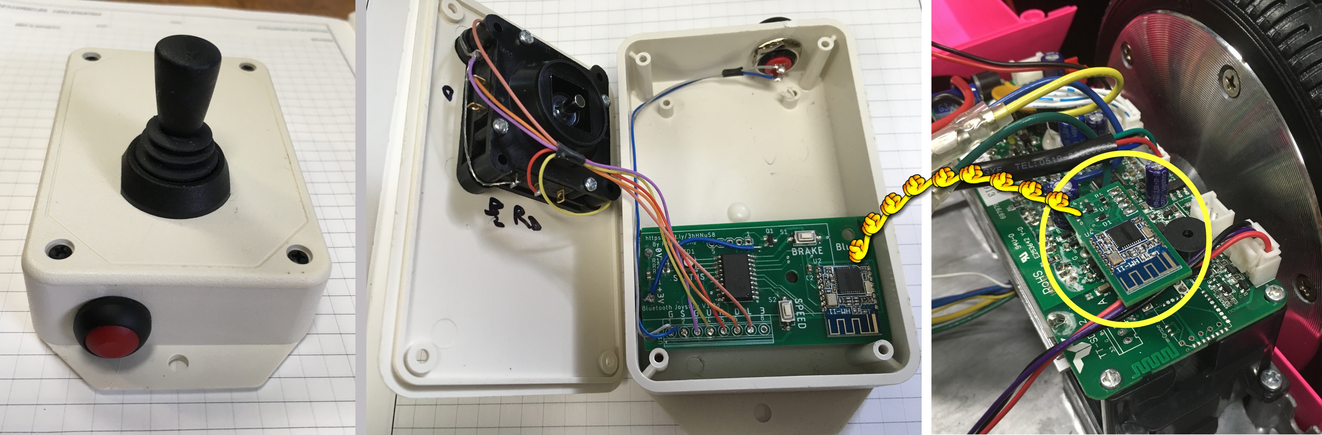
This picture shows the two parts of the BluJoy interface. The larger piece is installed in a plastic box with a joystick (the two AAA cells are located underneath the PCB). The Smaller piece is plugged into the Hoverboard Motor controller.
To check out the Eagle PCB, and PIC code, visit my Github repository and look at the BluJoy-PCB and BluJoy.X folders.
Discussions
Become a Hackaday.io Member
Create an account to leave a comment. Already have an account? Log In.