 Michael Möller
Theory
I'll think I start with the Program Counter. It is a counter. I happen to have a lot of 74LS197 (salvage from a surplus store) so I use one (or two) of them.
4 bit counter. I use the Arduino tester, to verify that I truly understand the chip. It actually is two counters; one single bit, and one with 3 bits. There is NO CARRY. OK, as the count clock is negative-edge sensitive it simply means putting the highest digit of the previous stage into the clock of the next counter.
The Clear will go to the global Reset line.
MicroSequencer
It will be another 74LS197 counter driven by the clock going into the 3->8 decoder 74LS138, where one of the 8 lines is high low for each tick. Route to each latch/tristate, with inverters, as appropiate. I hope that the "random logic" to get things happen at the correct clock edge will remain reasonably simple.
Implementation
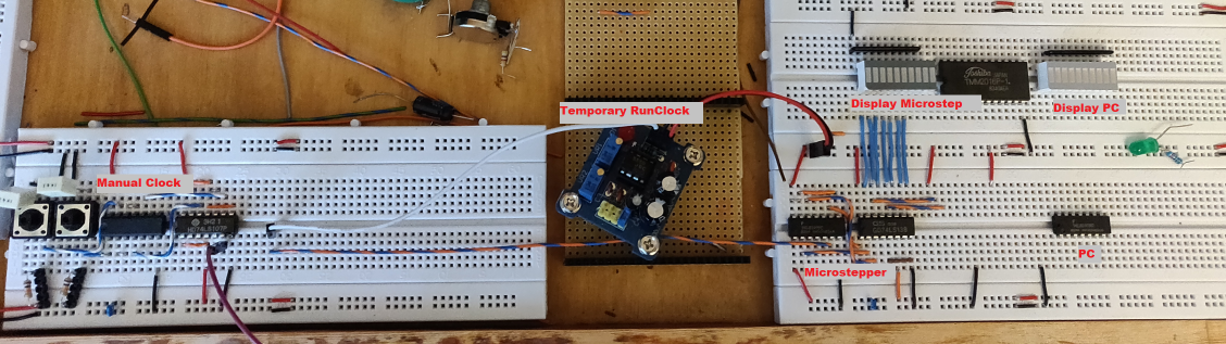
The microsequencer works as advertised, ie one of each of the 8 controllines go low at the desired step. (The rest is not on the above picture:) The PC gets the INC on step 2 and 4, and conditionally on step 6. Currently 4 ddressbits cycle correctly, address the RAM, and data can be stored and retrieved (for now by manually setting datalines and manually toggling WriteEnable). It is a 4bit machine for this phase, and the LED bar shows address and data.
The button debounce is giving me headaches - I cant get 100% releiable single step, and I do not know if reason is the button is too bad, the breadboard gives way/glitches, or I have stray signal pickup. (The latter seems likely - I sometimes get a "step" when touching some wire). It will do for the while being.
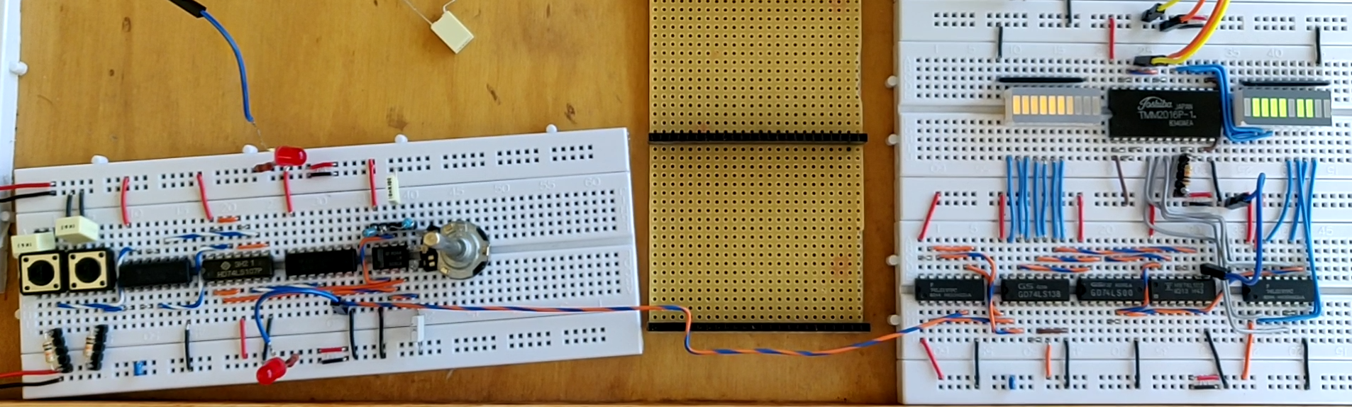
(Some while later): Clock works. The PC increments as it should at right microstep, including a manual simulated LEQ branch (ie do not increment, but the jump isnt there yet). Also the RAM access works. A manual (moving jumpers) load of data shows that read and write work.
The green display is temporarily both 4 bit address and 4 bit data. (Everything is 4 bit for the while being)
Discussions
Become a Hackaday.io Member
Create an account to leave a comment. Already have an account? Log In.