Close
0%
0%

ROVER-X

A STEM PROJECT

Similar projects worth following
A six wheel terrestrial rover that is true to the Rocker-Bogie Suspension, and the Ackerman Steering. Powered by a Li-Po battery and a Raspberry Pi, running servo motors at the wheels and steering joints, controlled by a tablet over a local network provided by an onboard router.

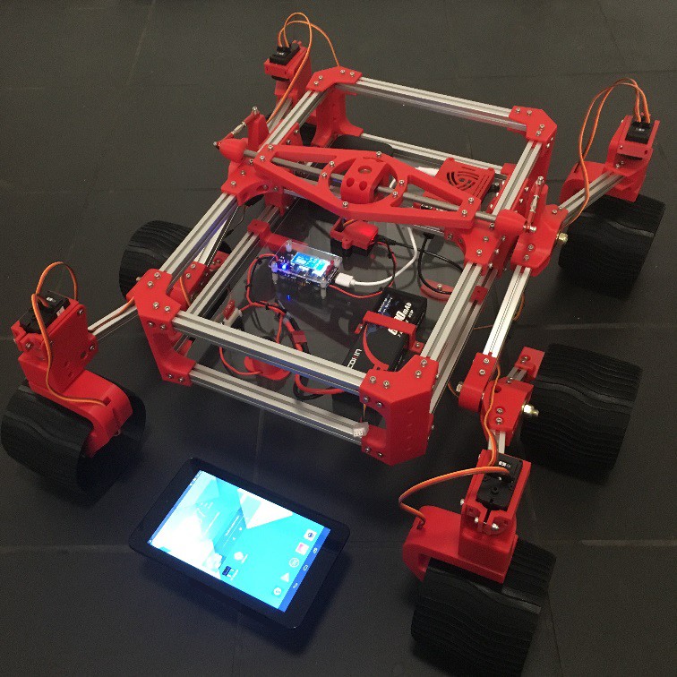
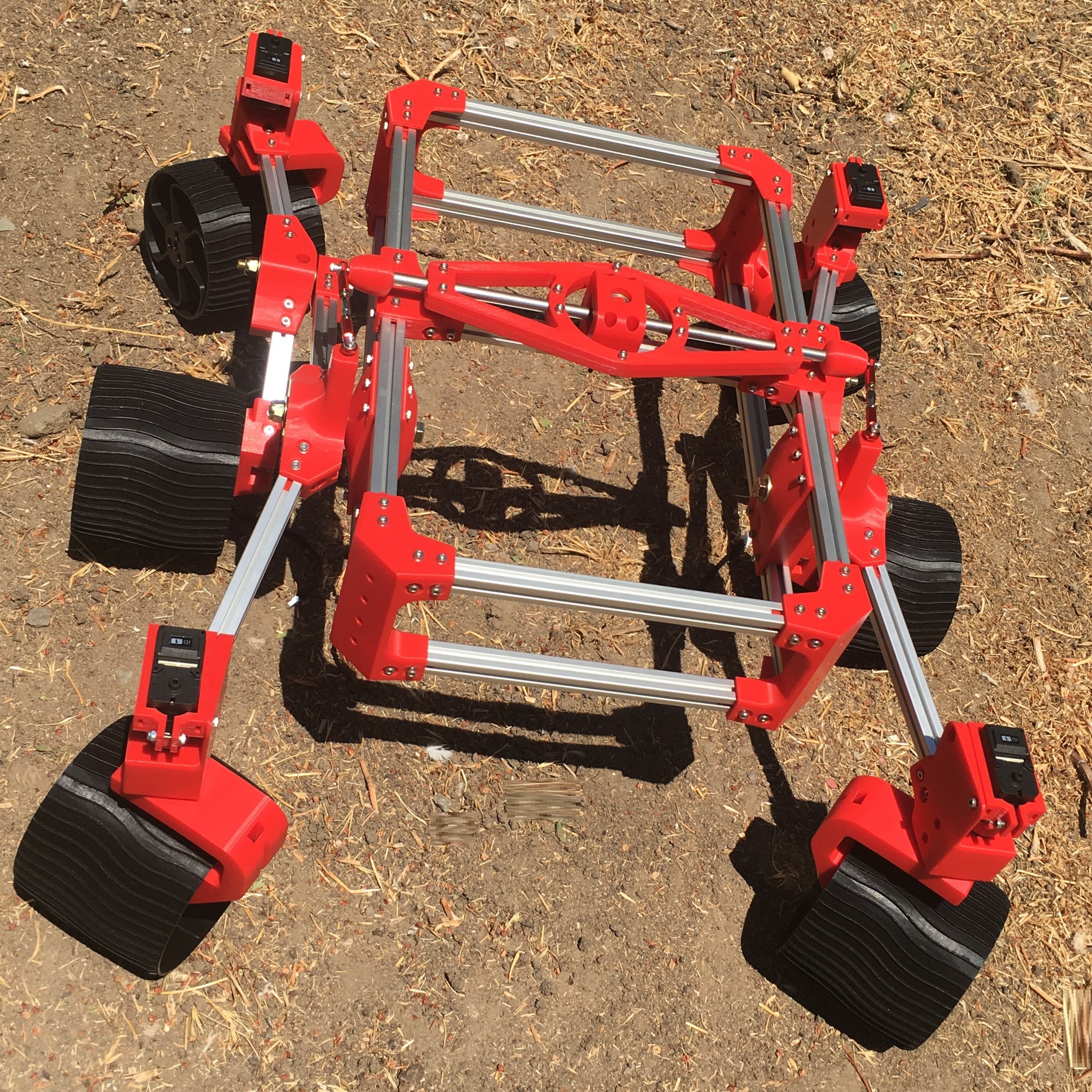
Rover-X is based on the schematics of the Sawppy Rover https://hackaday.io/project/158208-sawppy-the-rover by Roger (Thank you). A smaller Replica  that is true in proportions to the Curiosity rover.  ROVER-X will be used at a School Assembly Program to engage students in STEM related activities in Planetary Science featuring the mechanisms of all 4 rovers NASA sent to Mars.

-

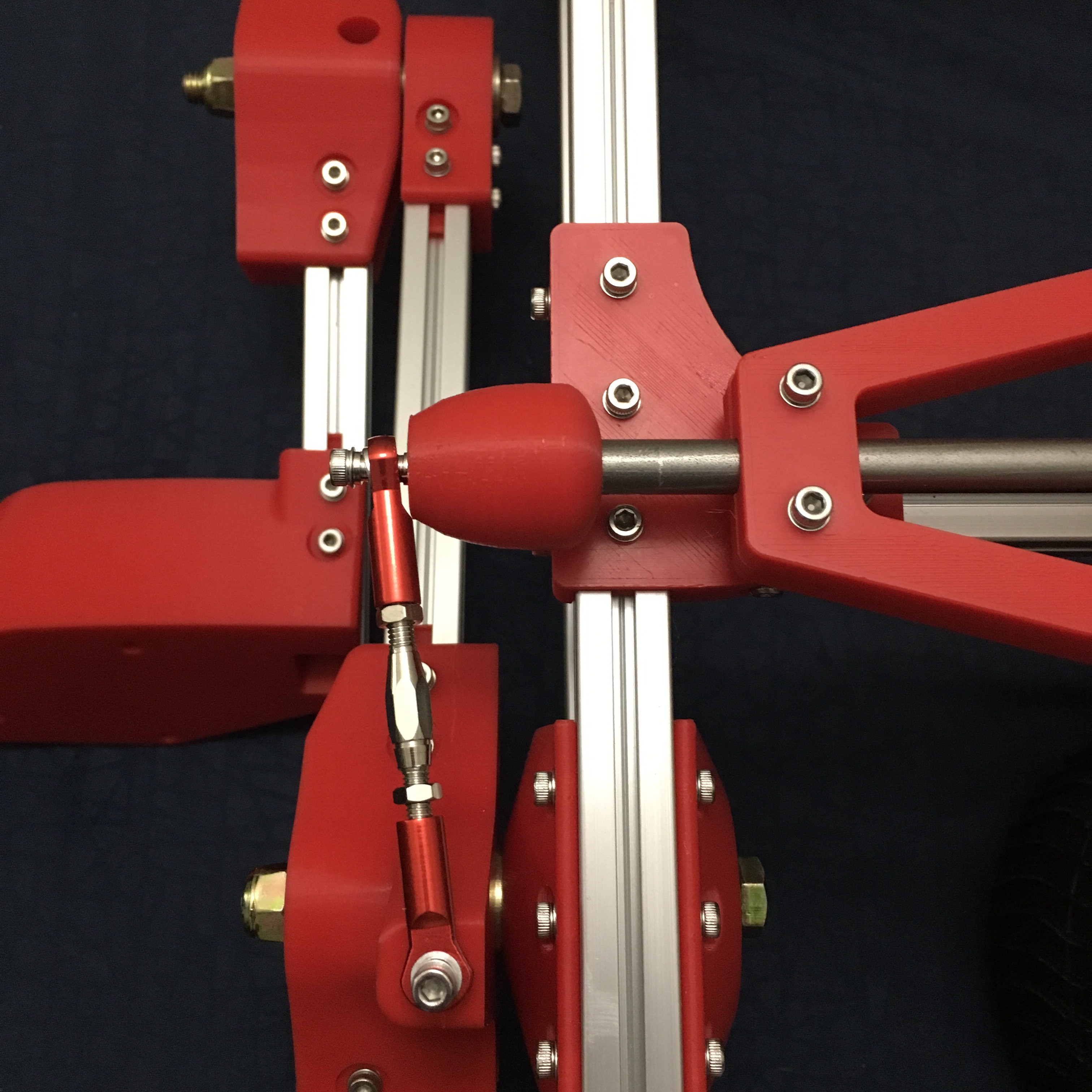
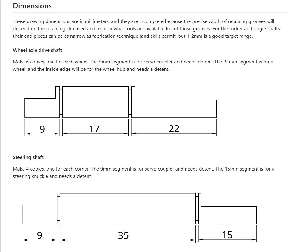
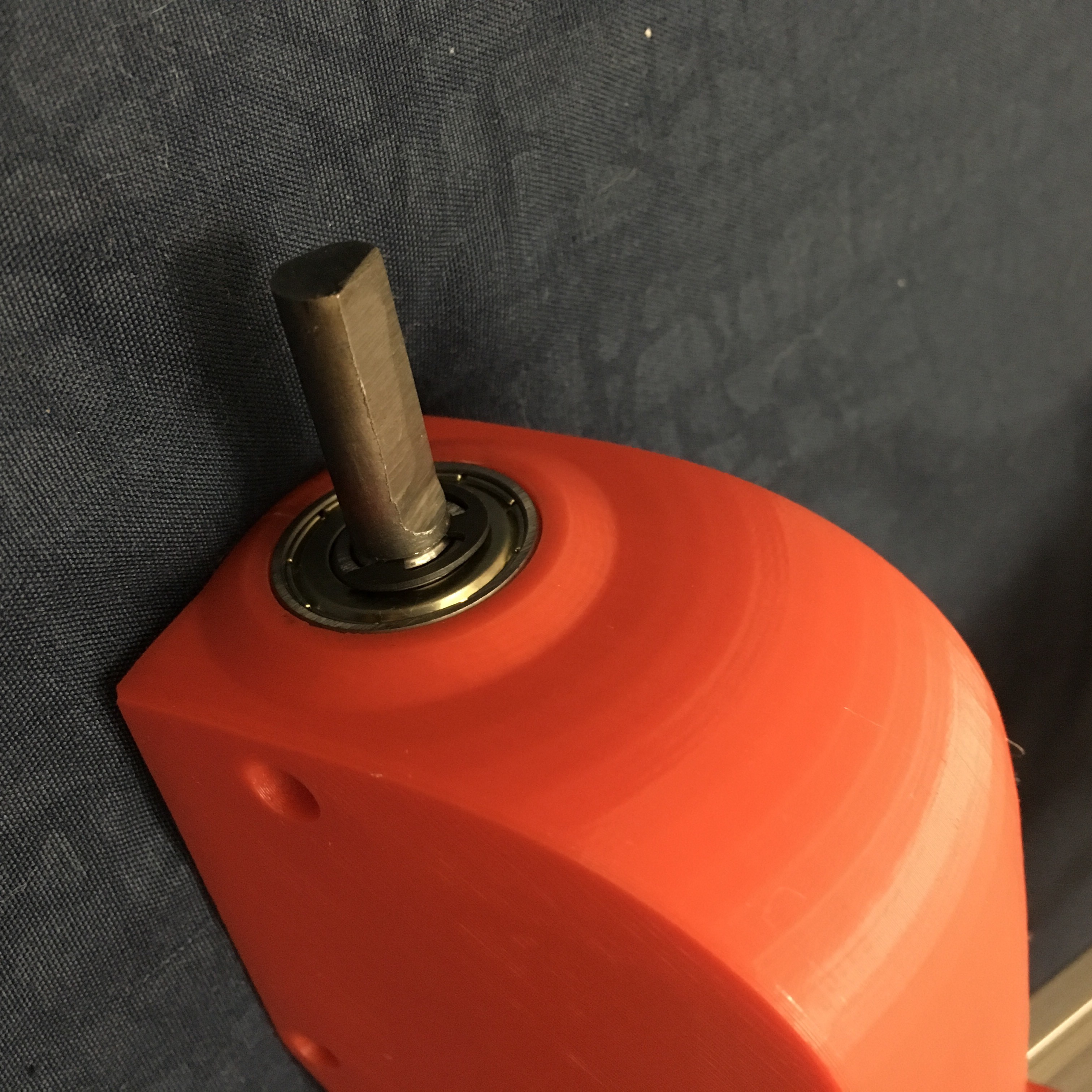
I built this rover in the late spring/early summer of 2020, so I had an advantage of seeing what others have done, and I tried to put together the best parts I can get my hands on and tried to do the least amount of fabrication possible (The only parts I had to fabricate were the 10 steel shafts attached to the servo motors, and those were shaved a little different than the ones on Sawppy 1.0). The total cost of all parts ended up being $600.

-

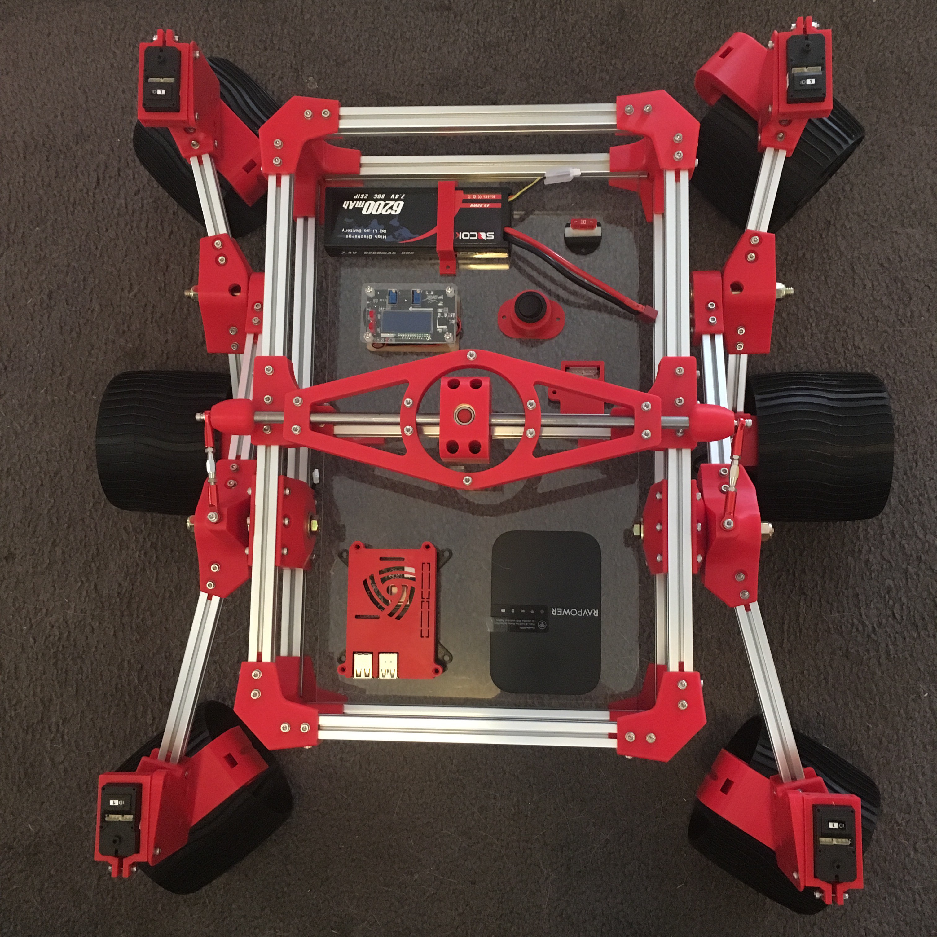
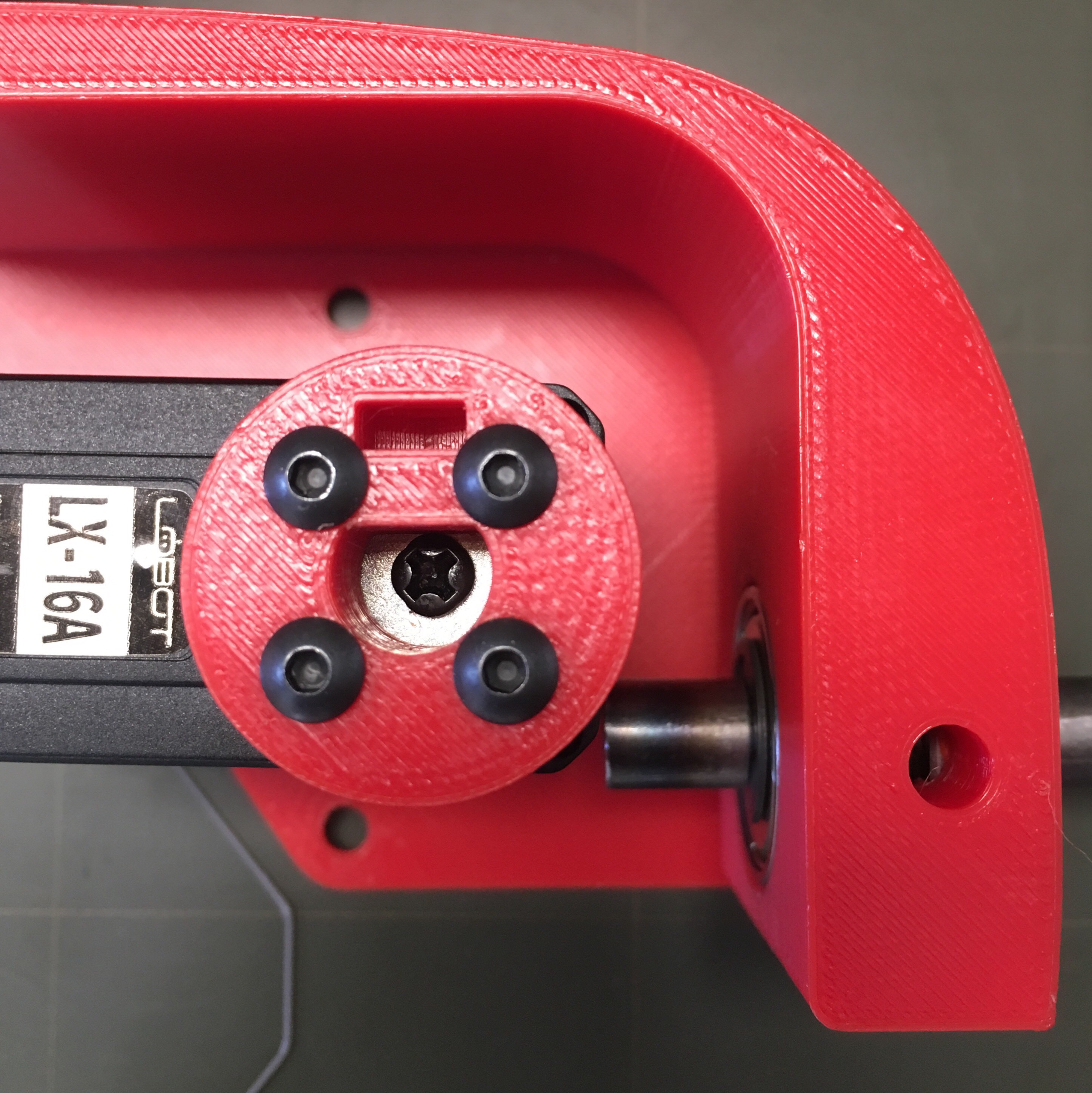
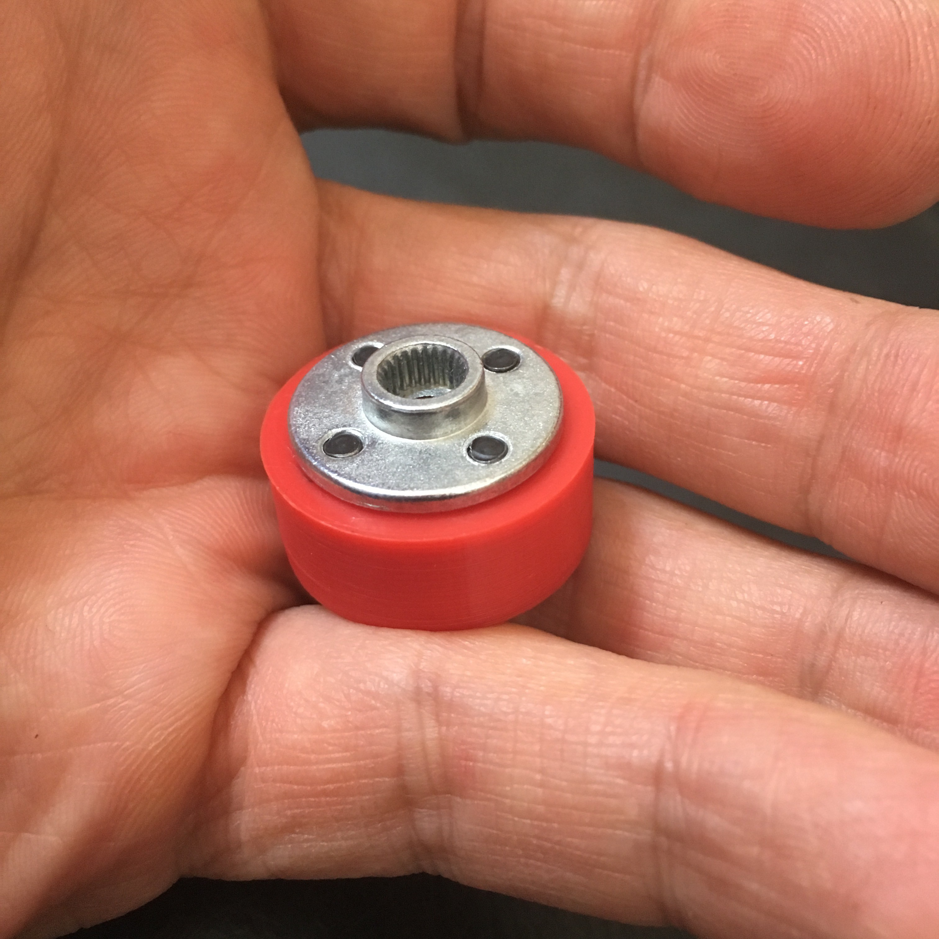
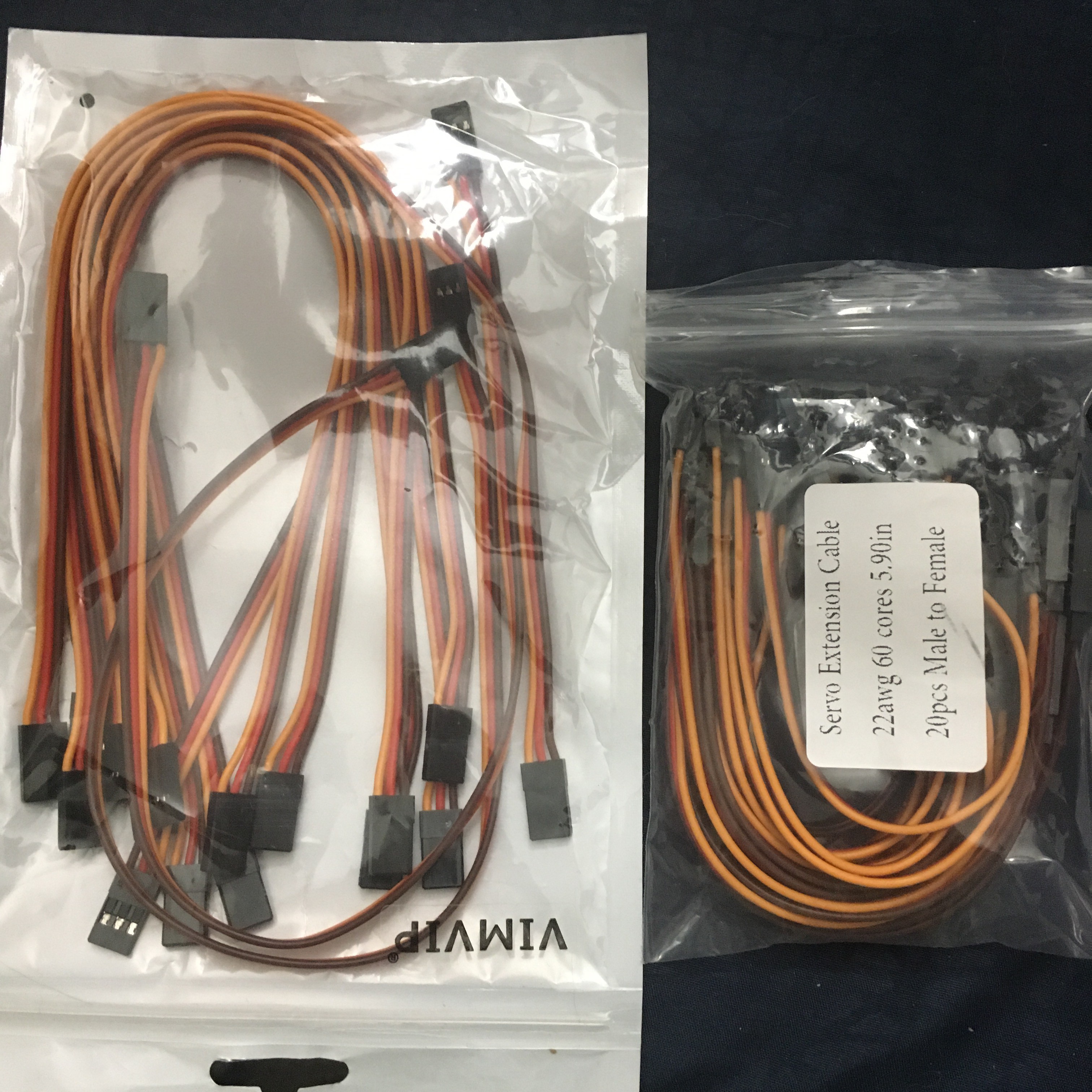
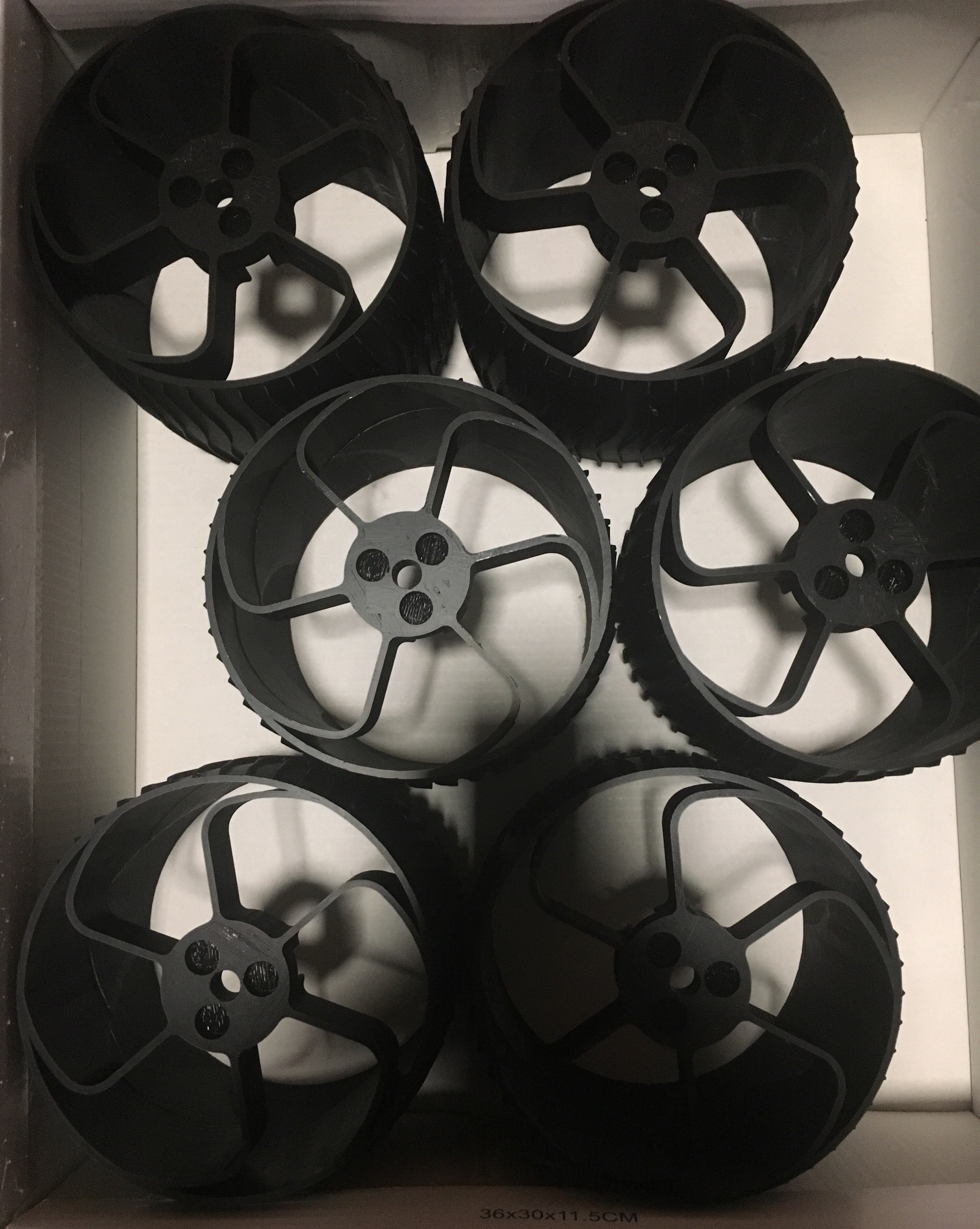
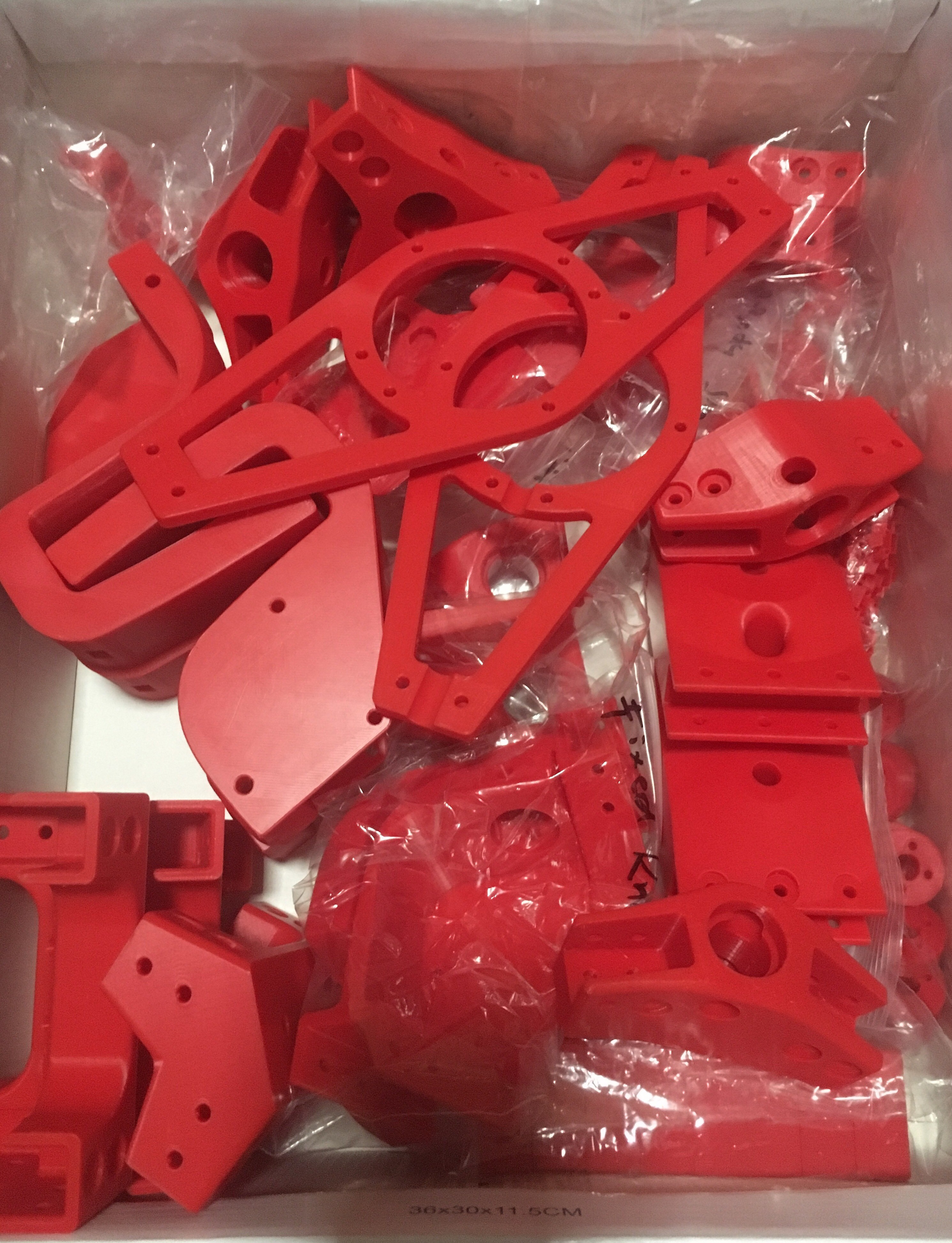
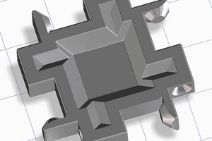
Regarding the Files: They are the 7 .stl files of the 3D Printed Parts I used on my rover that are different than those on the Sawppy 1.0.

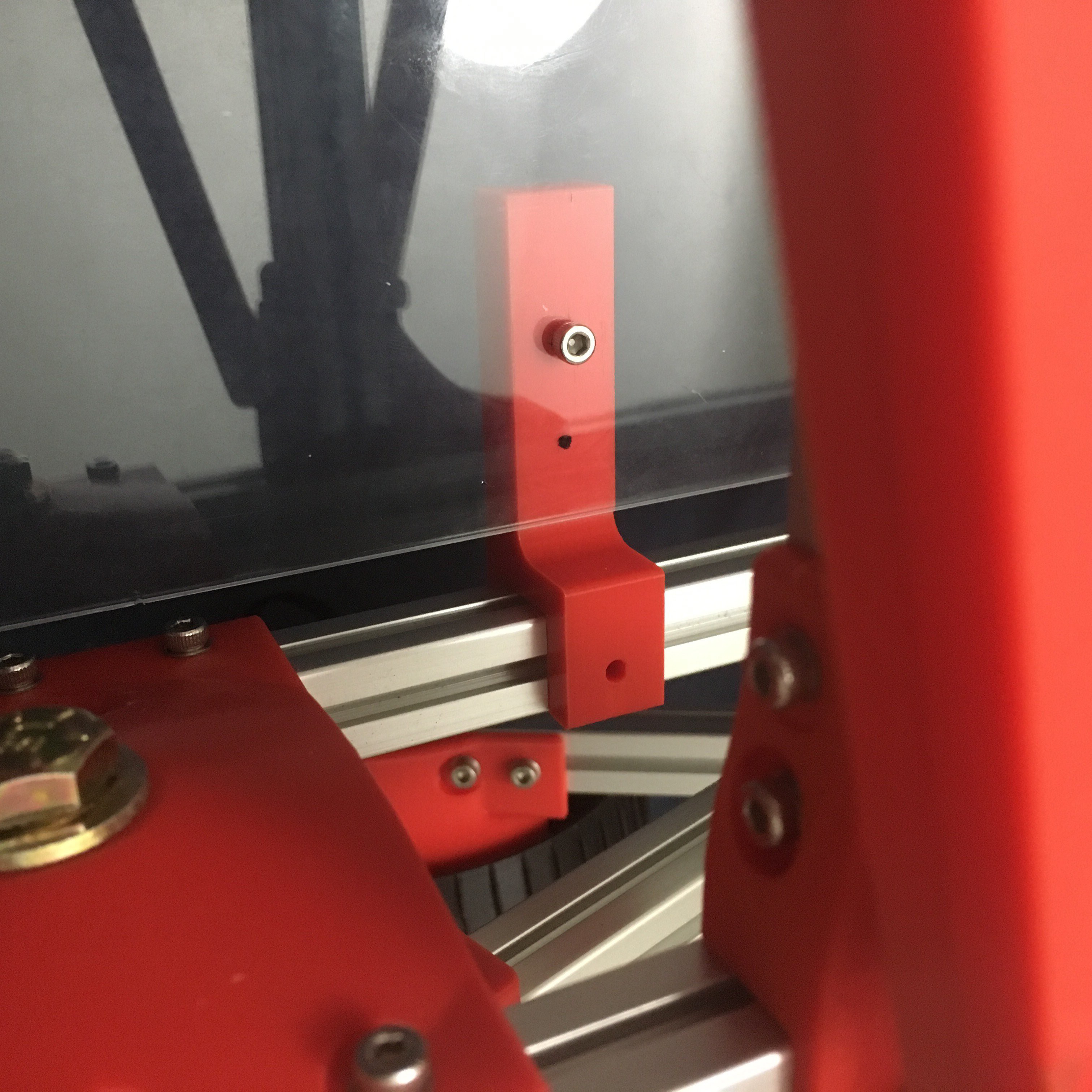
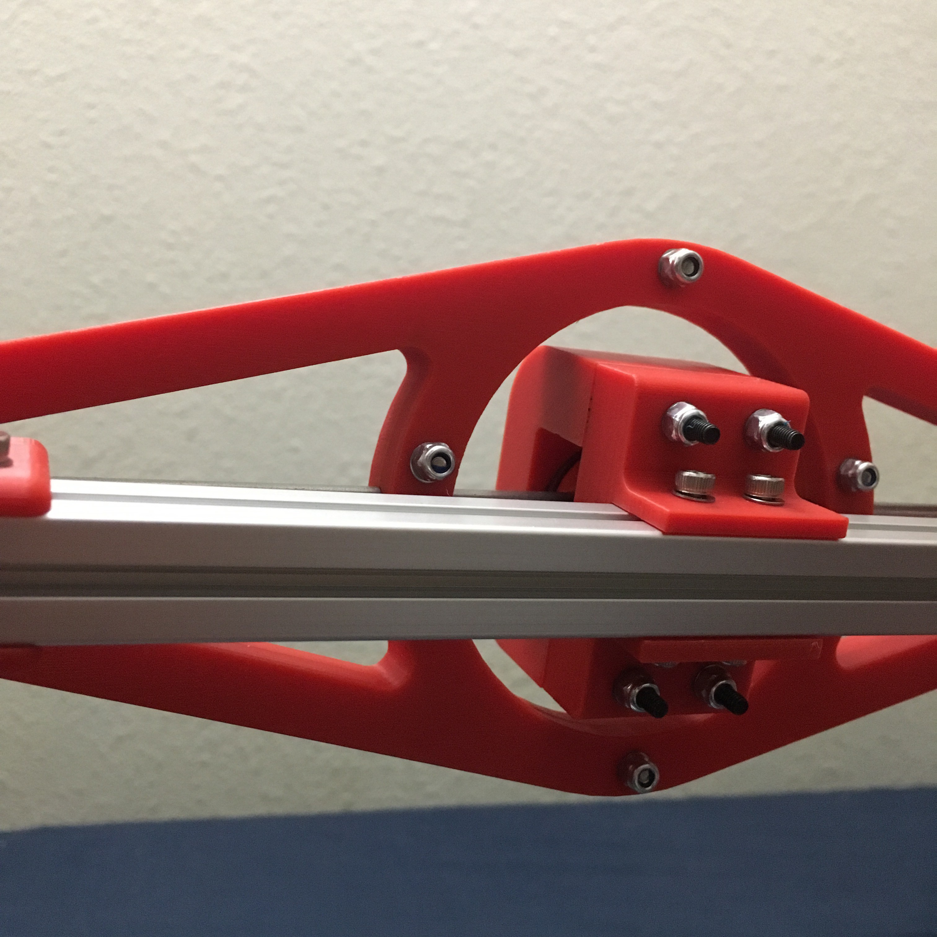
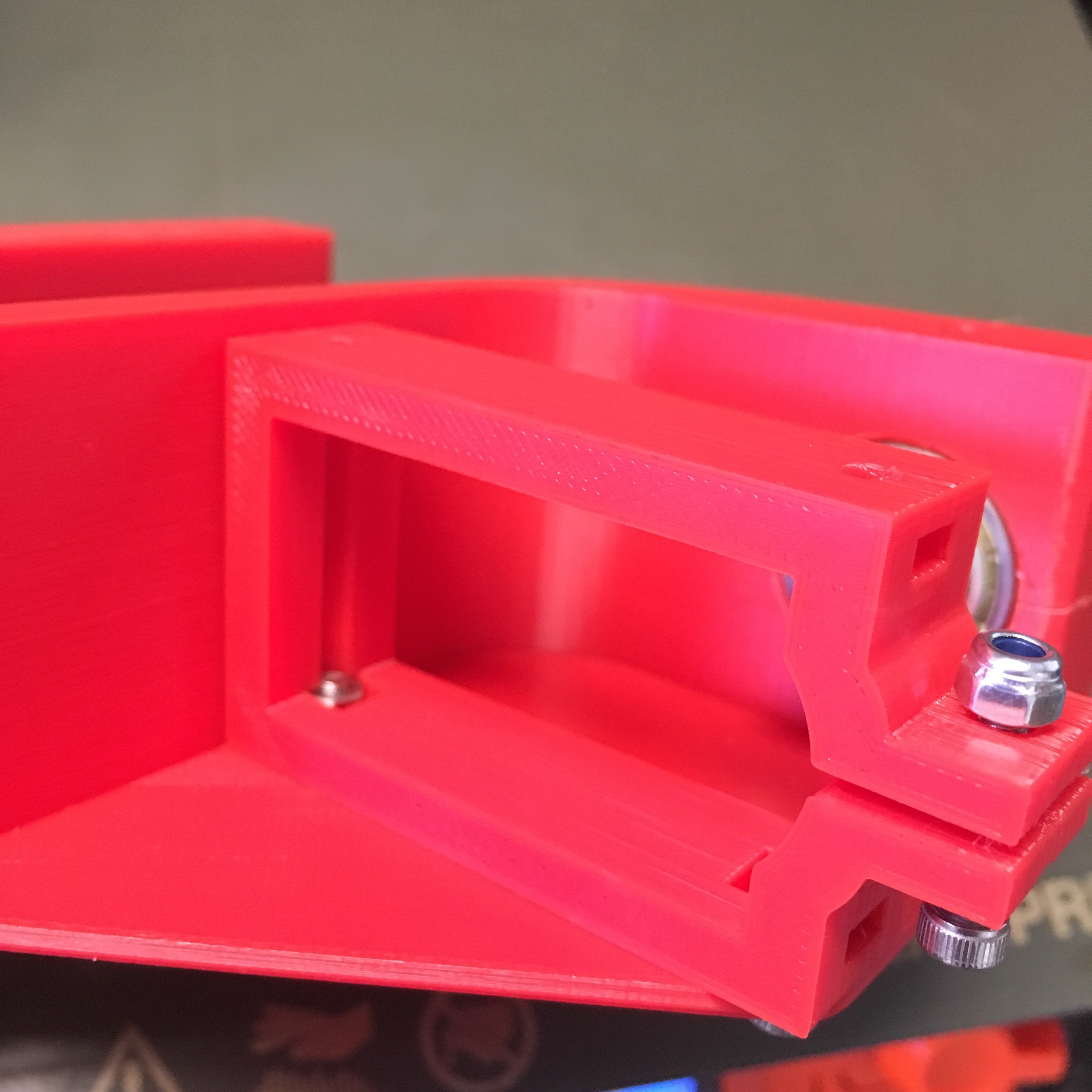
1 Designed from scratch: Servo Brackets

3 Designed similar to the Sawppy ones, I had to re-make the 3 Center Differential Parts because the Sawppy ones didn't fit properly.

3 Designed as Optional Parts: Two parts I created as Bus Linker Housing, and one is a Support Arm for the floor panel (two of those needed).

* Other Edited 3D Printed Parts: I also used 4 edited parts (files) from the CJ Rover ttps://hackaday.io/project/165094-cj-a-sawppy-variant (Thank you Laura).

As a Final note in regards to 3D Printed Parts, I didn't print the Battery & Power Tray from the original Sawppy, I placed those parts on the Rover's Floor Panel.

-

Regrading the Components:

I only listed the components I used on my rover that are not mentioned on the SAWPPY 1.0 components.

-

Regarding the Logs: In the 5 logs, I wrote about the progress of putting the rover together, and variations I addressed during the build. They appear here from most recent to oldest.

-

Regarding the Instructions:

My instructions are a timetable for the sequence of chores that can be utilized to efficiently move forward with the build as it takes shape.

Bus Linker Top.stl

Bus Linker Housing. Top Portion. You'll need 2 of the 24mm M3 screws, and 2 compatible Nuts - or you could use mini zip ties on these two parts if you like.

Standard Tesselated Geometry - 46.18 kB - 08/20/2020 at 21:58

Download

Bus Linker Bottom.stl

Bus Linker Housing, bottom portion.

Standard Tesselated Geometry - 60.24 kB - 08/20/2020 at 21:58

Download

FloorSupport.stl

Print two of these to support the Plex Glass floor of the rover, they go in the middle on both right and left sides, and use the 16mm M3 screws & Nuts we have been using.

Standard Tesselated Geometry - 33.38 kB - 08/03/2020 at 22:53

Download

Servo Bracket Final v2.stl

The original one uses two screws into the servo bracket to mount the bracket to the wall and mount the servo to the bracket. That design is not sound, this one uses slots for proper mounting, and a clamp for holding the servo.

Standard Tesselated Geometry - 57.11 kB - 07/27/2020 at 06:18

Download

DiffCenterJoint v1.stl

The original one is the wrong size. I made this one, it was a little tight so I needed to sand it a little with a fine sand paper, worked perfect after that.

Standard Tesselated Geometry - 224.79 kB - 07/27/2020 at 06:17

Download

View all 7 files

  • 10 × Servo Metal Horns I purchased and used metal horns, although the servos did come with plastic horsn.
  • 16 × Servo Wires with Connector Ends 10 male to male, 4 Split, 2 male to female Extensions
  • 4 × Screws and matching Washers and Locking Nuts For the Rocker and Bogie Shafts, instead of fabricating Steel Rods
  • 40 × Button Head M3 Screws To Connect the Metal Servo Horns to the Round Brackets
  • 24 × M3 Locking Nuts To use on the Differential Cross Members, and the Servo Brackets

View all 8 components

  • Power & Control Panel

    Ameer08/01/2020 at 08:40 0 comments

    After completing the mechanical assembly of the rover, a Raspberry Pi-4B computer and Several other components will be places on a panel inside the rover - ultimately connecting to the 10 Servo Motors that move the rover. It will be wirelessly controlled by a tablet that communicates with the rover over a local network using an on-board rechargeable router.

    -

    The Floor Panel I used for the rover is a 3mm thick clear plex glass piece.

    Size is 40cm x 23.5cm so it Slides in from either front or back of Rover Chassis box and fits perfect inside the Aluminum Extrusion Grooves. I 3D printed 2 simple middle Floor Support Arms (shown in the pic below). I uploaded an stl. for them with the other files.

    Here is a pic of the parts that will be within the rover's compartment, randomly placed on the floor panel:

    From top left: Battery, Fuse, Voltage Regulator, Power Button, Bus Linker, RPi-4B, and Router.

    I 3D printed a Bus Linker Housing Bracket (in two parts) to mount it to the floor pan, and cover it, I added the stl.s to the other files.

    -

    Note: For the Li-Po battery, you should purchase Connector Wires, and a Wall Charger.

  • Mechanically Complete

    Ameer07/29/2020 at 21:13 1 comment

    On July 28, 2020 the Rover finally stood strong on its own wheels, only two days before the launch of Nasa's Perseverance Rover to Mars.

    I want to thank Roger, Laura, and my brother Johnny for their support and help.

  • Non-Original Parts

    Ameer07/26/2020 at 20:07 4 comments

    The original design (Sawppy 1.0) works, but as Roger and a few others noticed some wear & tear they made recommendations.  In addition to all the 3D Printed parts that are edited and differ from Sawppy 1.0 here are some mechanical ones:

    * I bought and used Screws, Washers, and Locking Nuts for the Bogie and Rocker Joints, instead of using the Steel Shafts. They fit the Barings perfectly. 4 Screws, 4 Nuts, and 16 Washers.

    * I redesigned the 3 parts of the Central Differential joint because they were the only parts on the list of '3D Printed Parts' that didn't fit properly, I simplified the shape and made the top and bottom to accept 24mm M3 Screws and Locking Nuts. Only 4 needed (the black screws in the pic below). I also used locking nuts on all 10 Screws that combine the long differential cross members together (4 visible in the pic). I will be using locking nuts on other parts later, so if you copy this design get yourself two dozen M3 locking nuts.

    * I used 40 of the 12mm M3 Button Head Screws to mount the 10 Servo Couplers onto the Servo Metal Horns. They were those, from Ace Hardware:

    * I bought 10 Metal Horns  They were these https://www.amazon.com/gp/product/B07D56FVK5/. The same ones used on the CJ Rover (Thank you Laura), I used different screws on them than CJ had - so on my rover the screws go into the coupler first then exit and thread onto the metal horn.  In the pic below, they are the perfect length and they end up flush with the metal horns they screw into.

    * I used a 16mm M3 Screw and a Locking Nut for each of the 10 Servo Bracket Clamps that I redesigned to clamp the servos. Also visible are the two slots I designed for nuts to properly mount the bracket to the wall.

    * The shafts for all 10 motors: I shaved the same detents used on the CJ Rover, which are different than the original design (Shaved all the way to the edge on both ends). Those work with the original design parts, but work better with the couplers edited and printed for them in the CJ design, which I also used (Wheel couplers and Servo Couplers).

    The diagram is an edit from Roger's original diagram.

    * The main wiring harness connecting the Bus Linker to all 10 motors in parallel can be configured in several ways, I chose to buy wires with compatible connectors that plug into each other and create the needed harness without cutting any wires.

    The original connector name of the LX-16A servo is 5264-3Y. The 3 is for number of Pins, and the Y is a designation for the shape of the connector. I couldn't find long wires with end connectors that are 5264-3Y. 

    I believe they use these https://www.yoycart.com/Product/532736572990/  and those http://www.crazell.com/product/molex-5263-3p/ but I want my rover to have as many Plu-n-Play parts as possible, so I bought Universal Servo Wires: they fit tightly in the connector slot, have 3 pins that are separated by 2.5mm from one another, and they come in male-male wires, male-female extension wires, and splitter wires.

  • 3D-Printed Parts

    Ameer04/26/2020 at 03:52 0 comments

    My first assignment was to print the 3D needed parts. I used my Prusa MK3s and Red and Black PLA.  I printed 'ALMOST' all the parts from the .stl files posted by Roger. However, I used some variations:

    Mirrored Parts:

    I printed the 4 corner Knuckles mirrored to place the motors in symmetry, and at some point in the future I will be printing 3 wheels mirrored because unlike on the real curiosity rover our wheels have directional spokes.

    Edited Parts:

    I printed 4 components from the STL's edited by (CJ Rover) to accommodate enforced mounting of moving parts, two of those 4 components (Triangle Wheel Couplers, and Round Servo Couplers) I printed at 100% infill for Strength.

    I also printed 4 parts from my own redesign (The 3 parts in the Center Differential Joints), because the central differential joints didn't fit properly from the original .stl. I printed the bottom one in a different shape.  As I got close to mounting the servos and wheels I didn't like how the servos mount into the brackets or how the brackets mount into the walls; so I redesigned the Servo Brackets (and printed all 10 of them with 100% infill).

    Optional Parts:

    I printed a housing for the Bus Linker (2 parts) and Support Arms for the floor panel (2 identical arms)

    Did not Print:

    I did not print the Battery Tray or the Power Tray; I placed them inside the body of the rover.

    COSTS

    * 3D-Print the Parts Yourself $100

    I used less than 1KG of Black PLA for Wheels, and less than 2KG of Red PLA for all other parts. I Paid $75 on eBay for all 3KG Shipped, and my Printer used about $20 worth of Electricity. If you have a 3D Printer with suitable size bed you should be looking about the same of what it cost me.

    * Have someone 3D Print them for you $600

    Don't have a 3D-Printer? Don't want to learn the Slicer software? or deal with 2 Weeks of printing? I found a few places online, and this one seems reputable https://print.all3dp.com/ so I uploaded all the parts and the total was $600 for the Entire Set; Filaments, Tax, and Shipping Included.  I suppose you just have to instruct them which parts you want mirrored along the x-axis, and about the infill factor.

  • Raspberry Pi 4B

    Ameer04/25/2020 at 16:53 0 comments

    I decided to use the newest Raspberry Pi model as of today; the RPi-4B.

    It can be powered via the USB-C port, and it uses a Micro-HDMI to output display.  You will also need an 8GB Micro SD Card (or 16 or 32; I chose a 16GB), and an SD Card Sleeve for it.

    https://www.raspberrypi.org/downloads/

    Download The firmware Raspbian onto your PC, download Installer onto your PC as well, then run Installer and choose Raspbian as the firmware and the Micro SD Card as the place to install its image. Your SD card is ready to be placed into your RPi and you can now run your RPi as a small computer; connect a usb keyboard and a usb mouse and a screen to it, turn it on; the user interface looks like any Windows PC.

    -

    NOTE: If you buy a Pi4-B make sure you also buy or have:

    HDMI- Micro-HDMI Chord

    USB-C power & chord with 5 volts and 3.1 amps

    Gen 10, micro SD card  & SD Sleeve

    You will need a USB Keyboard and a USB Mouse later to use the Pi

View all 5 project logs

  • 1
    Buy all the parts you need at the same time, and as soon as the filament arrives, start printing​
  • 2
    When the Steel Rods arrive, measure them, cut them, and shave them for the parts needed

    This is the only fabrication required.

  • 3
    When the Raspberry Pi arrives, install Raspbian on it

View all 7 instructions

Enjoy this project?

Share

Discussions

Ryan Kinnett wrote 08/20/2020 at 23:26 point

Hi Ameer, fantastic job!  It's absolutely beautiful.

  Are you sure? yes | no

Ameer wrote 08/20/2020 at 23:34 point

Thanks Ryan, what is the page for the Micro Rover you have on your page?

  Are you sure? yes | no

Ryan Kinnett wrote 08/20/2020 at 23:43 point

Good question. I built that a few years ago, before I joined hackaday.io, and haven't set aside time to write it up. Maybe I'll do that to share some of the project's interesting features. The build quality isn't nearly the same as yours. I built it mainly as a development platform for various control schemes, and I had big plans for autonomous mapping and such, but it all fell by the wayside when my daughter was born and now it's just collecting dust on my desk. Yeah, I think I will post a short writeup in case someone finds it useful. You've inspired me.

  Are you sure? yes | no

Ryan Kinnett wrote 08/21/2020 at 02:45 point

Here it is, hot off the press!

https://hackaday.io/project/174405-micro-rover

  Are you sure? yes | no

Similar Projects

Does this project spark your interest?

Become a member to follow this project and never miss any updates