 James Wilson
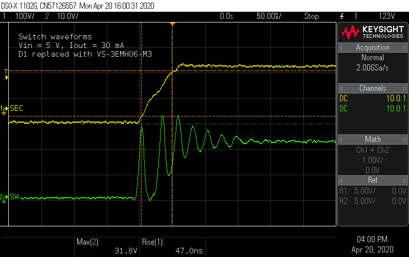
I got a shipment with the 600 V-rated ES1J and the VS-3EMH06-M3 diodes. How does a "hyperfast" rectifier compare to the "ultrafast" part I started with? Looking at the voltage on the rise time on the secondary shows it's close to twice as fast (47 ns vs. 90 ns). Already it appears the switch node ringing is starting at a higher amplitude.
 Probing the switch node shows a ringing waveform that looks much closer to the simulation. At the maximum inductor current condition, the voltage spikes are still 10% below the MOSFET Vds limit, without any snubber.
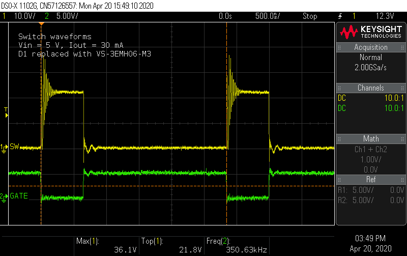
Lastly, the reverse recovery situation looks about the same, with the reverse voltage spiking to 530 V.
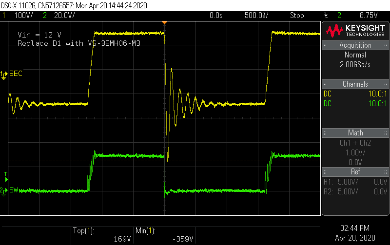
Overall, it seems this new diode is nothing special by comparison, but the 600 V rating is important given the voltage ringing during reverse recovery.
Efficiency measurements
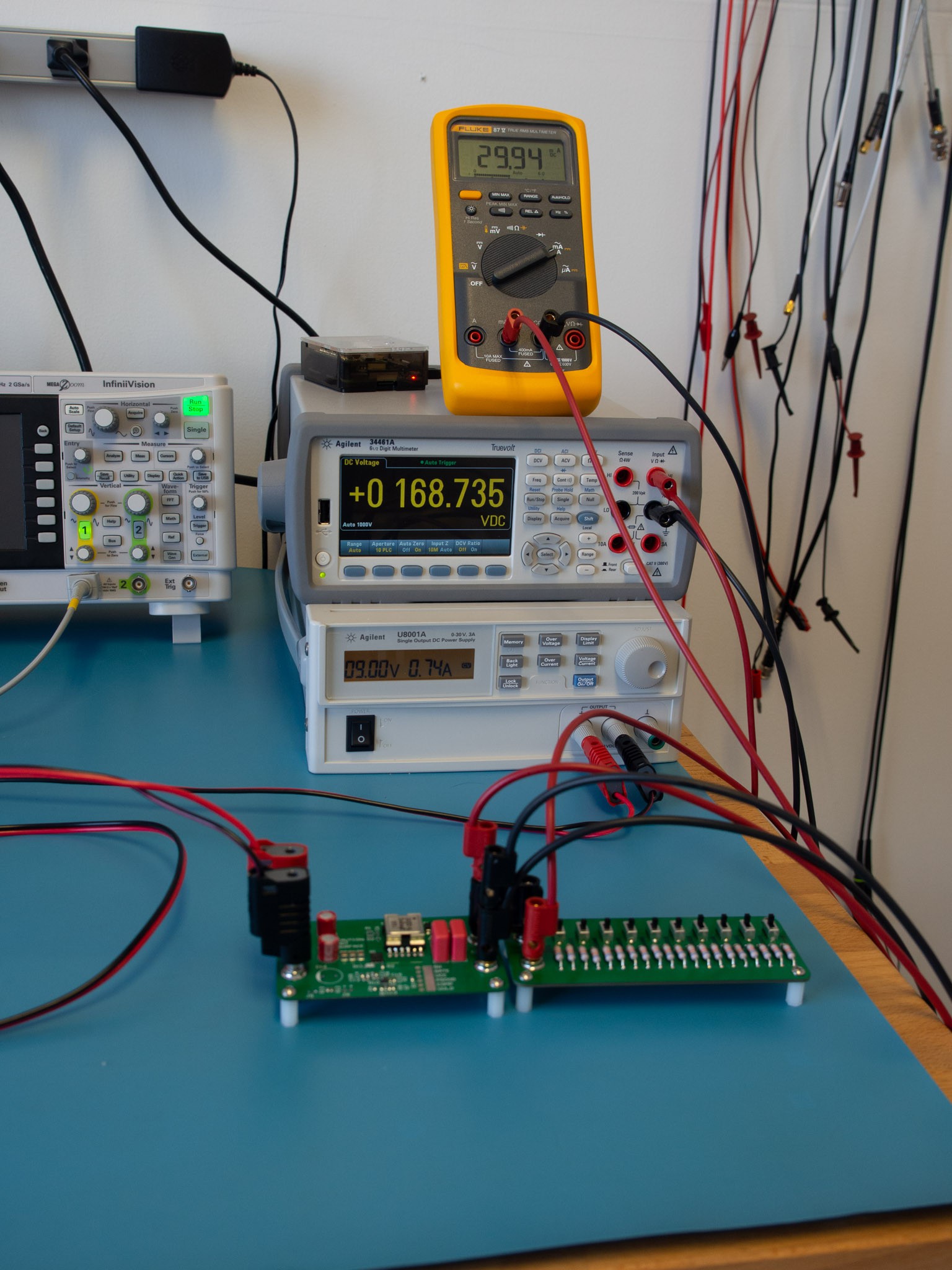
I waited to make efficiency measurements because I wanted to settle on a configuration to use after considering options for the snubbers or other adjustments. For this test, the measurements were taken with the VS-3EMH06-M3, and without RCD snubber network. I used the source display on my bench power supply to read the input power, and measured the voltage at the converter's output terminals and the current between the converter and load board. Of course, it'd be nice to do all this with ATE that would gather the data while I made on some coffee, instead of by hand ... perhaps someday.
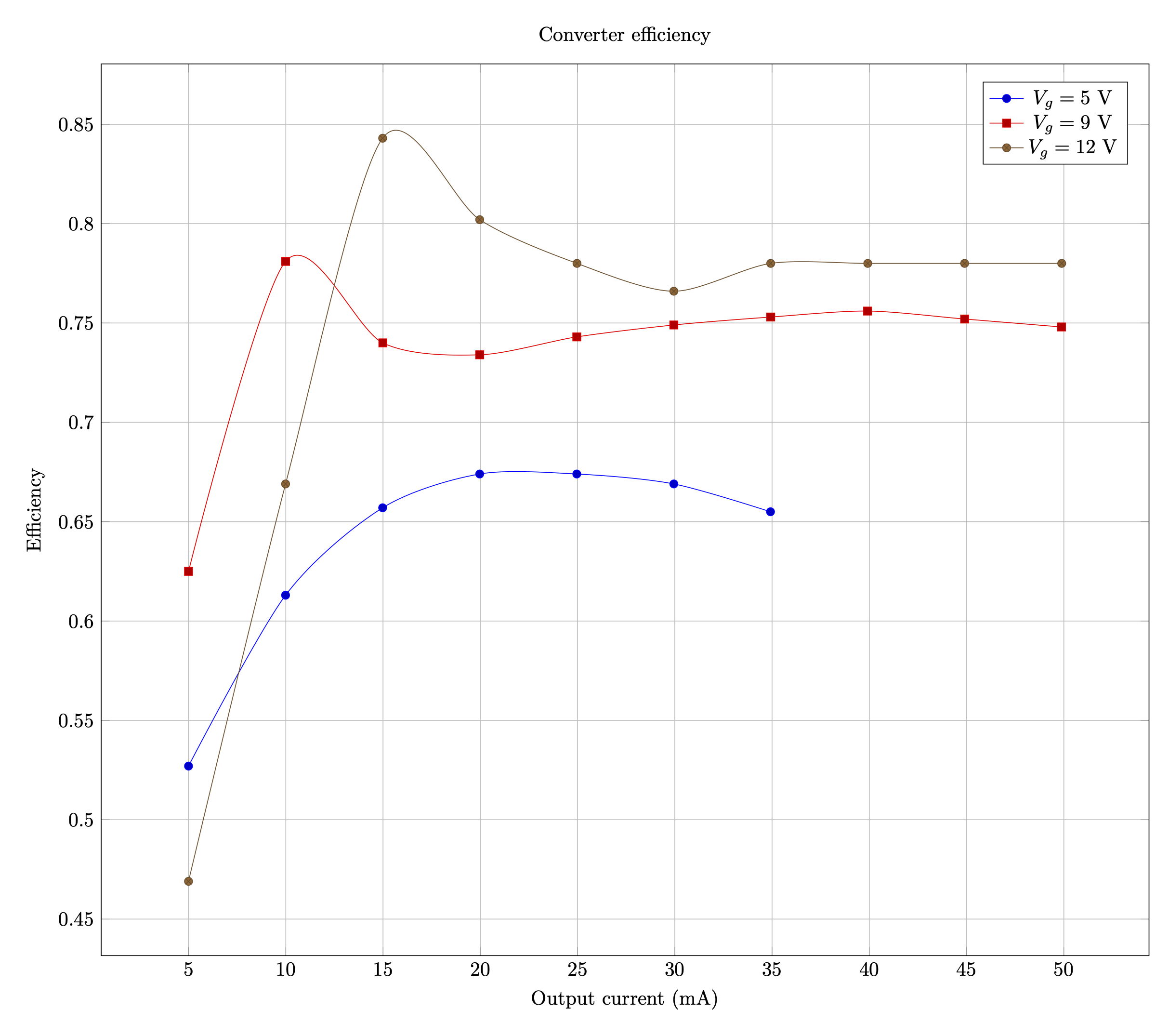
At 9 and 12 V, the converter is about 75-80% efficient, with a sweet spot around 15-20 mA where it peaks over 80% with 12 V input. It would have nice to be consistently above 80%, but it appears core losses in the transformer are the limiting factor. It is easily the warmest component on the board during operation.
I didn't take measurements at 5 V beyond 35 mA, because at high load, the current in the transformer is high enough that causes a thermal runaway. Heat increases resistance and voltage drop, so the converter adjusts by increasing duty cycle and average current, which further increases heat. Eventually the converter hits the current limit or the transformer core begins to saturate. At the 5 V, the converter should be thermally derated to 25 mA maximum current to keep the transformer from overheating, unless active cooling is done.
The last parts experiment I had was to test polypropylene (PP) output capacitors. PP is supposed to have lower dissipation factor by an order of magnitude compared to polyethylene terephthalate (PET), so it should handle pulse currents better. Would it help improve efficiency beyond the 75-80% level? I replaced the output caps and reran the efficiency experiment. The result was basically a wash. A few fraction of percentage points here, a few there. No data point changed by more than 1 %, which doesn't justify their added cost.
Discussions
Become a Hackaday.io Member
Create an account to leave a comment. Already have an account? Log In.