 James Wilson
While I'm waiting for the rev B boards, I tried an experiment to reduce the switching frequency to investigate its effect on efficiency. I replaced the timing resistor (R8) with a 150 kΩ resistor, which coincidentally, yields a 150 kHz switching frequency on the LM5155.
At lower switching frequencies, the converter will run in discontinuous conduction mode (DCM), which means the current in the inductor goes to zero in the off state. DCM makes much of the mathematics more difficult, and requires reevaluation of many component choices, but also has some positive effects. I ran the calculations for the current sense network and found the same sense resistor works. One of the consequences of current programmed control in DCM is it is stable without any artificial ramp. Nonetheless, simulation showed the converter is in CCM during startup, so the original slope compensation resistor choice prevents subharmonic oscillations. The compensation network will need changes, but an analytical model of transfer function of the CPM-DCM flyback converter will need some work. For this experiment, simulation showed the existing compensation network is adequate for stability.
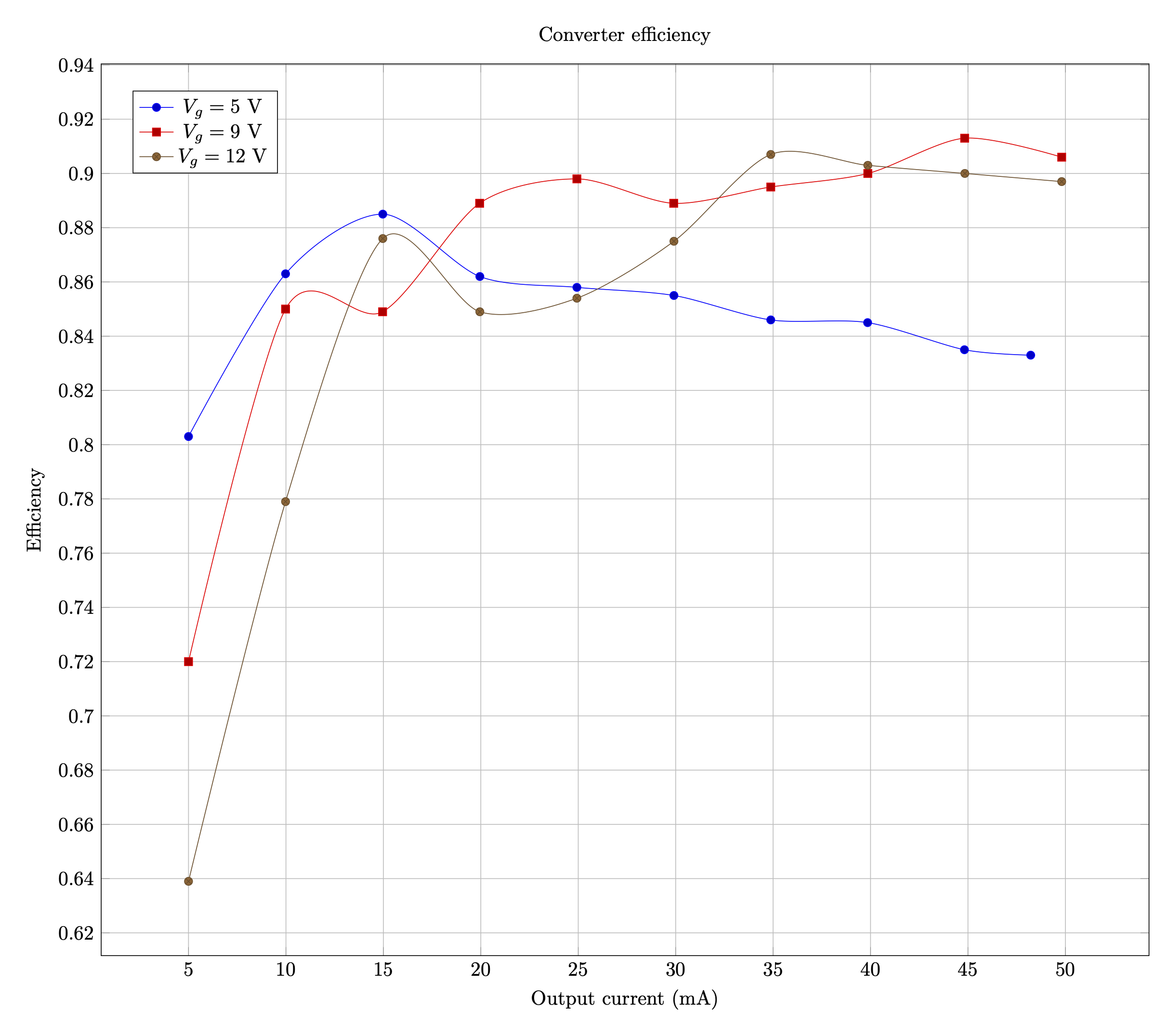
I performed the efficiency measurement again, and the results speak for themselves. The lower switching frequency and DCM operation greatly improves performance. The converter achieves peak efficiency over 90% and is in the mid- or high- 80% range across the input voltage range! The transformer remains noticeably cooler, and while the converter hit the current limit at Vg = 5 V and R = 3.4 kΩ (what should have been 50 mA output), it did not show the same thermal runaway.
Discussions
Become a Hackaday.io Member
Create an account to leave a comment. Already have an account? Log In.