 James Wilson
I thought i called it a wrap on this project, but there were still a few small things to investigate. Here are the changes I made, which now puts things in a finished state.
Increase switching frequency to 120 kHz. At 100 kHz, the peak current on the transformer primary side would exceed its saturation rating (3 A). In DCM, the peak current is independent of the input voltage. Based on an load current of 30 mA, 120 kHz provides a better solution for keeping the primary-side current within datasheet limits.
Changes to current sense network: increase R_sense to 33 mΩ and remove R_SL (use a 0 Ω jumper). DCM is stable without an artificial ramp, but simulations showed the converter can drop into CCM for transients at low input voltage. Unfortunately, there is no combination of R_sense and R_SL that simultaneously limit the peak current to 3 A and guarantee stability in CCM at this low frequency, while respecting the 2 kΩ limit on R_SL. The biggest transient is at startup, and CCM operation can be prevented there with a generous soft-start time. Simulations showed effects on the load-step transients were tolerable, so I decided to use a R_sense, R_SL network that would solve for the peak current limit only. As a consequence, it's expected the output voltage will droop when the load current exceeds 30 mA as the LM5155 is limiting the current to protect the transformer core from saturating. The lower switching frequency also means a larger filter capacitor is possible, so C11 was increased to 22 nF.
Increase soft-start capacitor to 47 nF. Simulations showed a longer startup time keeps the converter out of CCM during startup. This choice more than doubles the startup ramp time to about 5 ms.
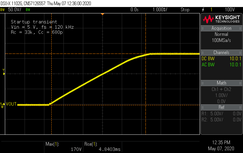
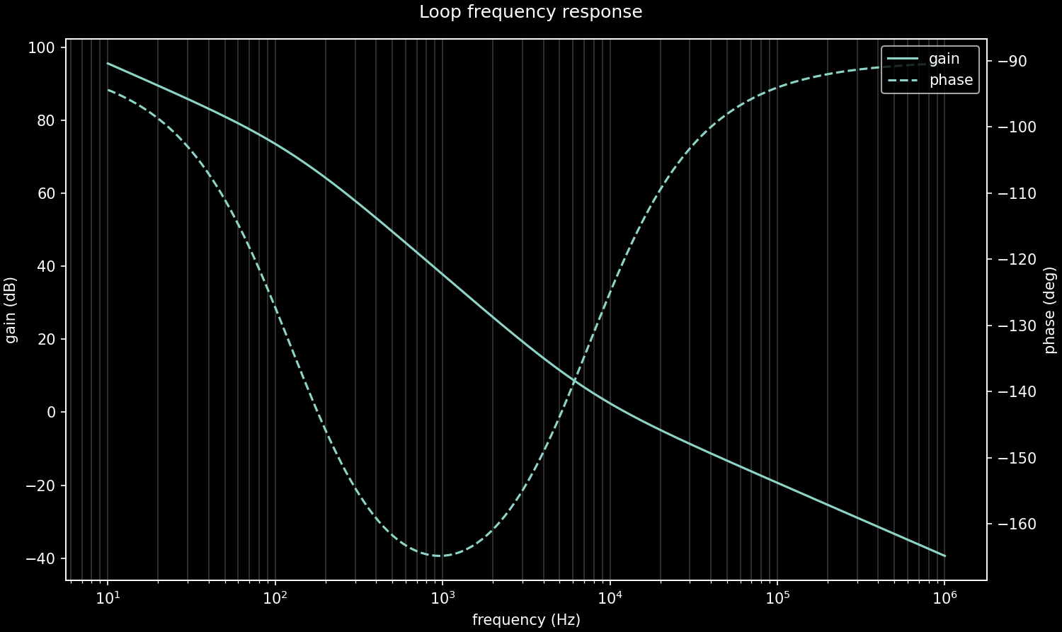
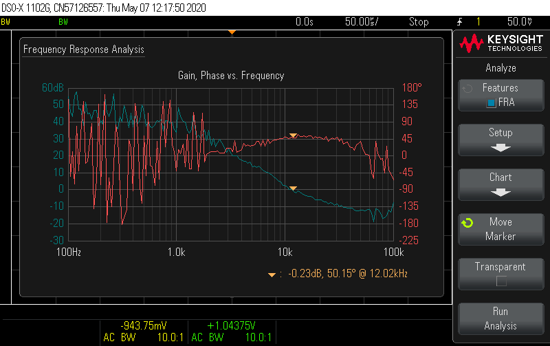
Improve compensation network. I derived an analytical small-signal model of the flyback in DCM-CPM, which informed better choices of the compensation network. I also made an error in the previous script and forgot to include the PWM gain factor (parenthetically referenced in tiny text on the LM5155 datasheet ... thanks TI). In DCM, the low-frequency behavior of the loop is approximately a single-pole system, with identical gain and pole frequency to a buck-boost controller. Without a RHP zero in the model, there is no obvious and natural choice for a HF pole, so I removed the second capacitor and used R = 33 kΩ and C = 680 pF to set the crossover at 12 kHz with 60° phase margin. These charts show the predicted and measured results. The converter now reacts to 5 mA load steps so fast, it wasn't even possible to capture them on the scope.
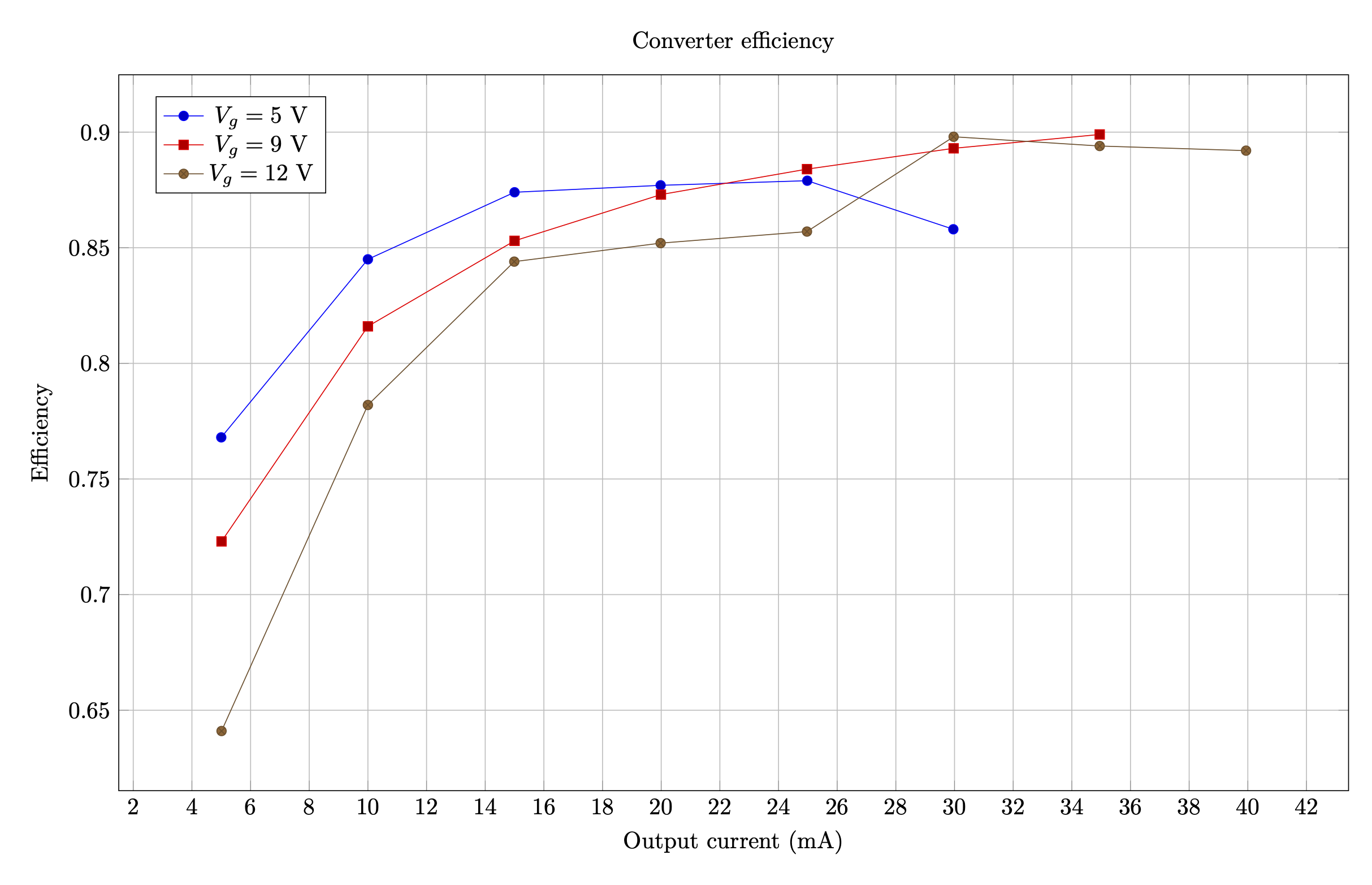
These changes deliver a small hit to the efficiency and limit the output current, but this is to be expected. The converter still achieves about 90% efficiency at high loads at 9V and 12 V input. Efficiency calculation were omitted after the converter hits the current limit.
Discussions
Become a Hackaday.io Member
Create an account to leave a comment. Already have an account? Log In.