James Wilson
-
Going ... discontinuous
04/28/2020 at 04:58 • 0 commentsWhile I'm waiting for the rev B boards, I tried an experiment to reduce the switching frequency to investigate its effect on efficiency. I replaced the timing resistor (R8) with a 150 kΩ resistor, which coincidentally, yields a 150 kHz switching frequency on the LM5155.
At lower switching frequencies, the converter will run in discontinuous conduction mode (DCM), which means the current in the inductor goes to zero in the off state. DCM makes much of the mathematics more difficult, and requires reevaluation of many component choices, but also has some positive effects. I ran the calculations for the current sense network and found the same sense resistor works. One of the consequences of current programmed control in DCM is it is stable without any artificial ramp. Nonetheless, simulation showed the converter is in CCM during startup, so the original slope compensation resistor choice prevents subharmonic oscillations. The compensation network will need changes, but an analytical model of transfer function of the CPM-DCM flyback converter will need some work. For this experiment, simulation showed the existing compensation network is adequate for stability.
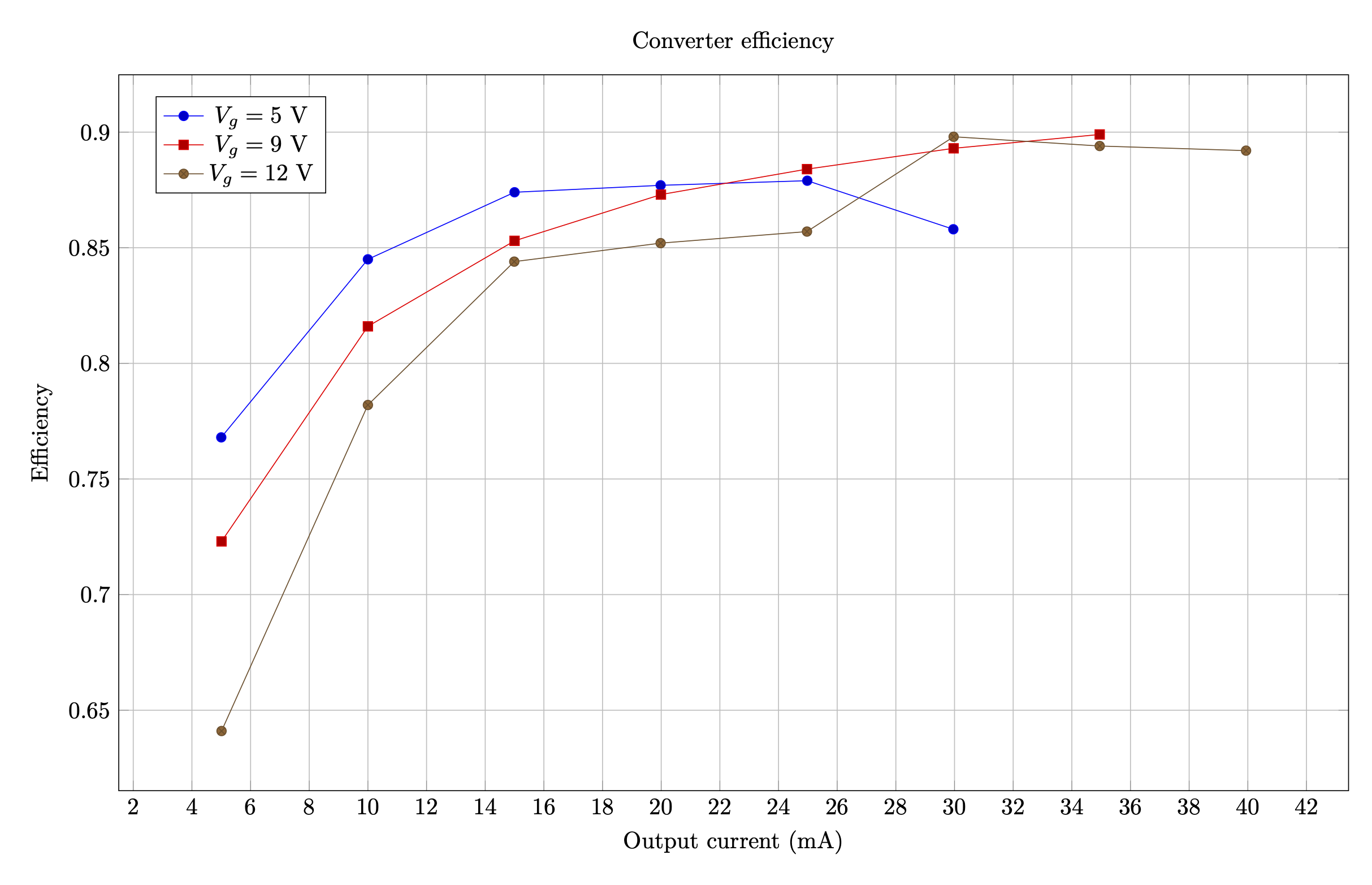
I performed the efficiency measurement again, and the results speak for themselves. The lower switching frequency and DCM operation greatly improves performance. The converter achieves peak efficiency over 90% and is in the mid- or high- 80% range across the input voltage range! The transformer remains noticeably cooler, and while the converter hit the current limit at Vg = 5 V and R = 3.4 kΩ (what should have been 50 mA output), it did not show the same thermal runaway.
![]()
-
Rev. B evaluations and wrap-up
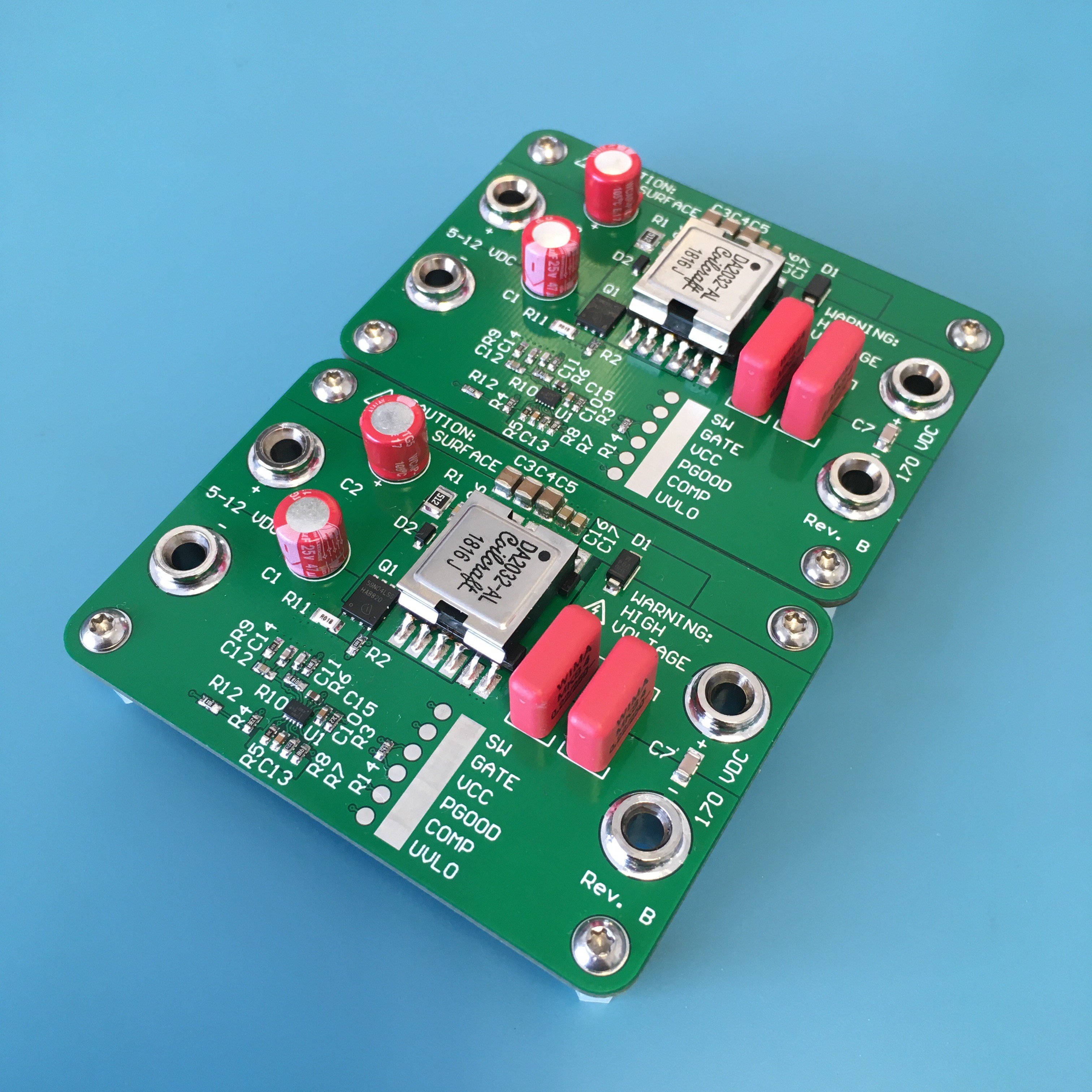
04/30/2020 at 01:49 • 0 commentsThe rev. B boards arrived and I assembled three of them with the remaining parts. The differences are subtle:
- the input capacitors have been moved adjacent to the transformer, with a clear return path on the bottom side ground pour
- loop gain circuit was scrapped and replaced with a single 20 Ω series resistor for use with an injection transformer
The resulting board is slightly smaller.
![]()
Experimental validation of the feedback loop bandwidth
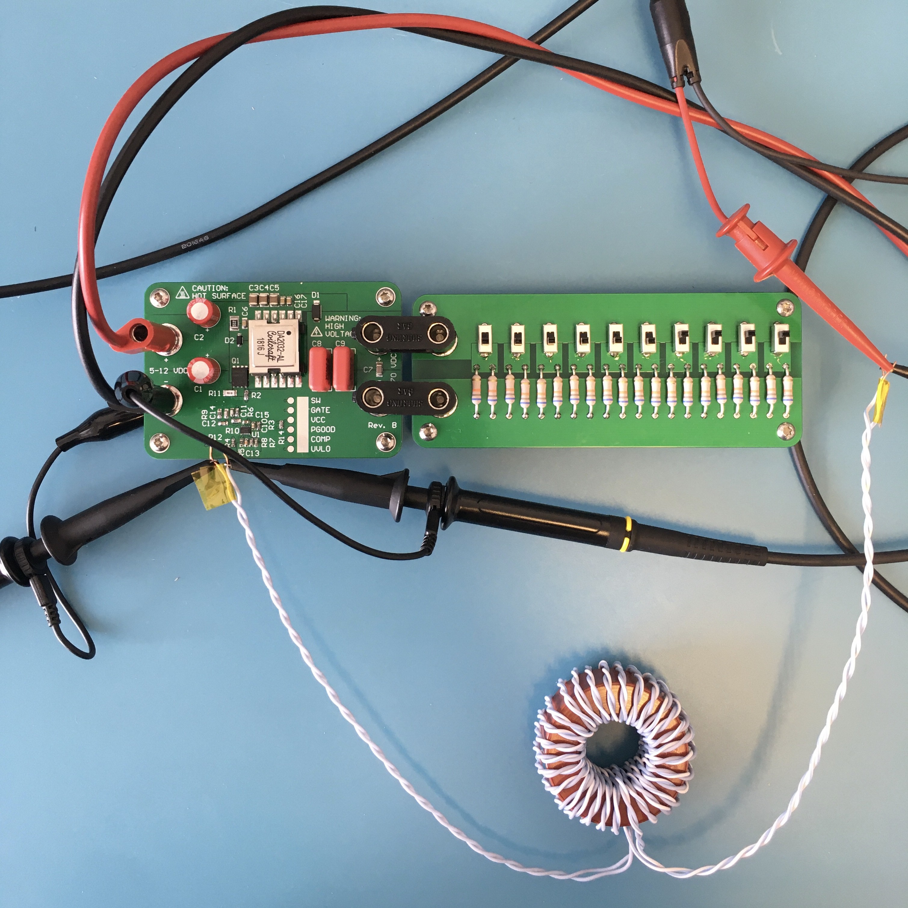
After all the modelling done in a previous section, how good was it? Following the procedure in AN-1889, I connected a 1:1 injection transformer across R12. This transformer is a homebrew device with a bandwidth of 40 Hz - 2 MHz. One side was connected to my scope's built-in function generator, and the other side was soldered across R12. I used the oscilloscope's frequency response analysis tool to produce a Bode chart of the converter's feedback loop.
![]()
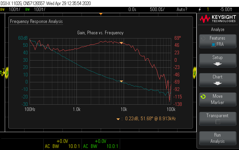
For the original configuration in the design work (fs = 350 kHz, Vin = 5 V, Iout = 30 mA), the measurement shows crossover is at about 9 kHz with a 51° phase margin. The model prediction was crossover at 8 kHz with a 60° phase margin. The shape of the gain and phase curves shows good agreement to the model. If I were going to keep using this configuration, I might tune the compensator's zero frequency to get a little closer to the target phase margin.
![]()
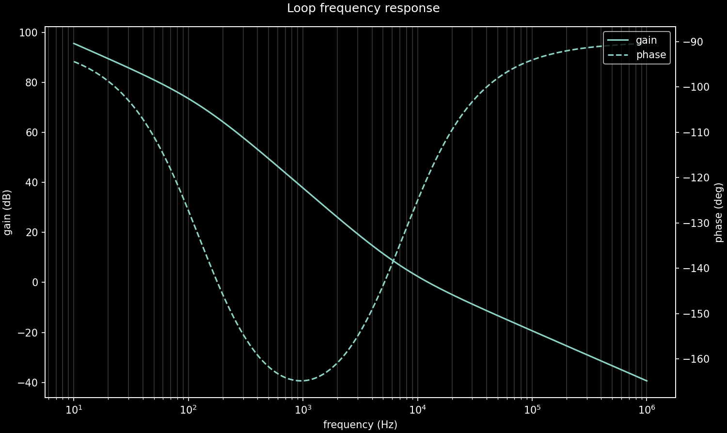
For comparison, here is the model prediction:
![]()
One of the changes I explored was dropping the switching frequency to improve efficiency. The LM5155 can go as low as 100 kHz, and I made an experiment with fs = 150 kHz earlier, noting that the compensation network might need adjustment. Now that I have the means to measure the loop from a point of relative stability, why not try the practical approach of tuning the components from a real circuit? After the amount of work that went into modelling the CCM transfer function, I'm in no hurry to do a model for DCM if only a minor adjustment is required. The remaining boards run at 100 kHz, so I repeated this experiment at Vin = 5 V, Iout = 30. The results are almost identical.
![]()
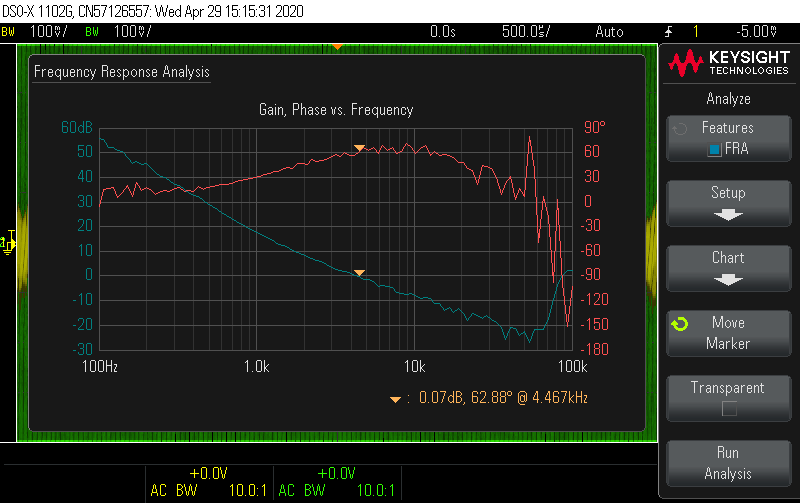
To see how DCM affects the loop dynamics, next I put the converter as deep into DCM as I could by running it at the highest input voltage and lowest current (12 V input and 5 mA output). Here the crossover frequency drops to shy of 5 kHz, with a healthy phase margin.
![]()
Before wrapping up this test setup, I also looked at middle-of-the-road configuration: 9 V input, 25 mA output current.
![]()
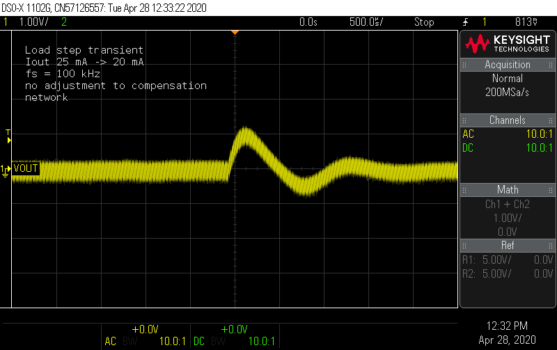
My conclusion is to stick with the current compensation network. Often what happens with DCM is the right-hand plane zero gets kicked out beyond the switching frequency, so using 1/10*fs is a common choice for the crossover, and this shows it's already set close to 10 kHz with a good phase margin. The step load transients (measured on rev A adjusted to 100 kHz) show good response in the time domain as well.
![]()
![]()
Revisiting voltage ripple and primary snubber
One of the changes was to improve the layout around the input capacitors. For comparison with rev. A, this time I measured the input ripple across the input capacitors, both converters operating at 100 kHz. This shows about half the ripple, with the smaller 1 µF capacitors taming some of the spikes.
![]()
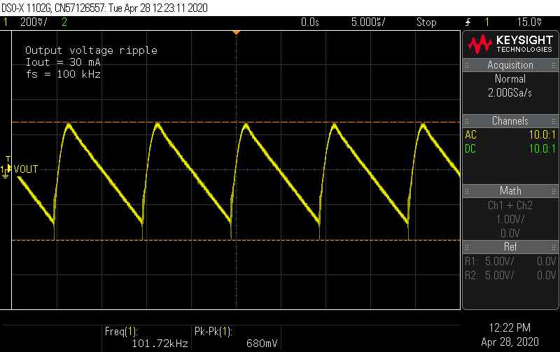
A lower frequency means increased output ripple since I didn't change the output capacitance. At 100 kHz, the voltage ripple increases to 1.4 V (p-p) at full load. This is still less than 1% of the DC level, and Nixie tubes do not need flat DC. Nonetheless, this could still be improved by increasing capacitance, with some possible adjustment required to the feedback loop. In this this package, film capacitors up to 470 nF are available, which would roughly double the output capacitance. For the target application, I'm fine keeping the pair of 220 nF caps.
![]()
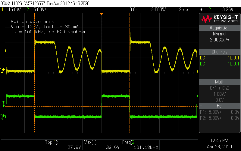
While looking at rev. A modified to run at 100 kHz (with the snubber removed), the switch node voltage saw peaks approaching 40 V, presenting concerns given the Vds rating of the MOSFET.
![]()
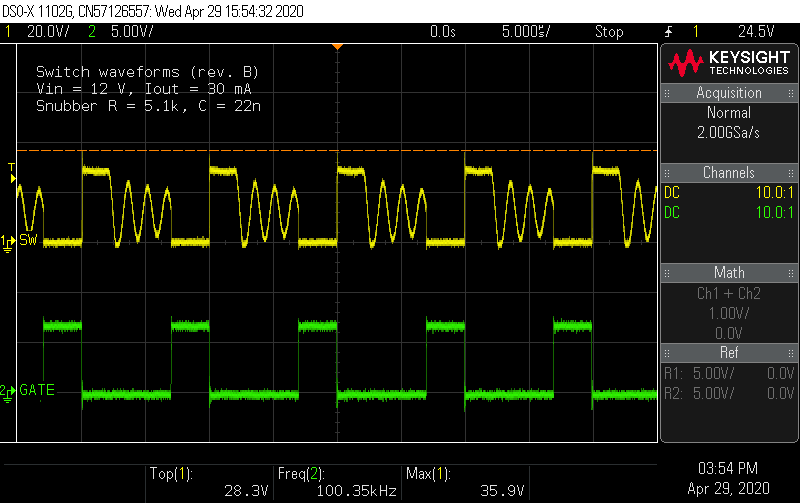
I placed the snubber components for the rev. B boards, and measured the switch node voltage at the highest level configuration (12 V input, 30 mA output). This keeps the switch node voltage at 90% of its rating.
![]()
Final efficiency measurements and conclusion
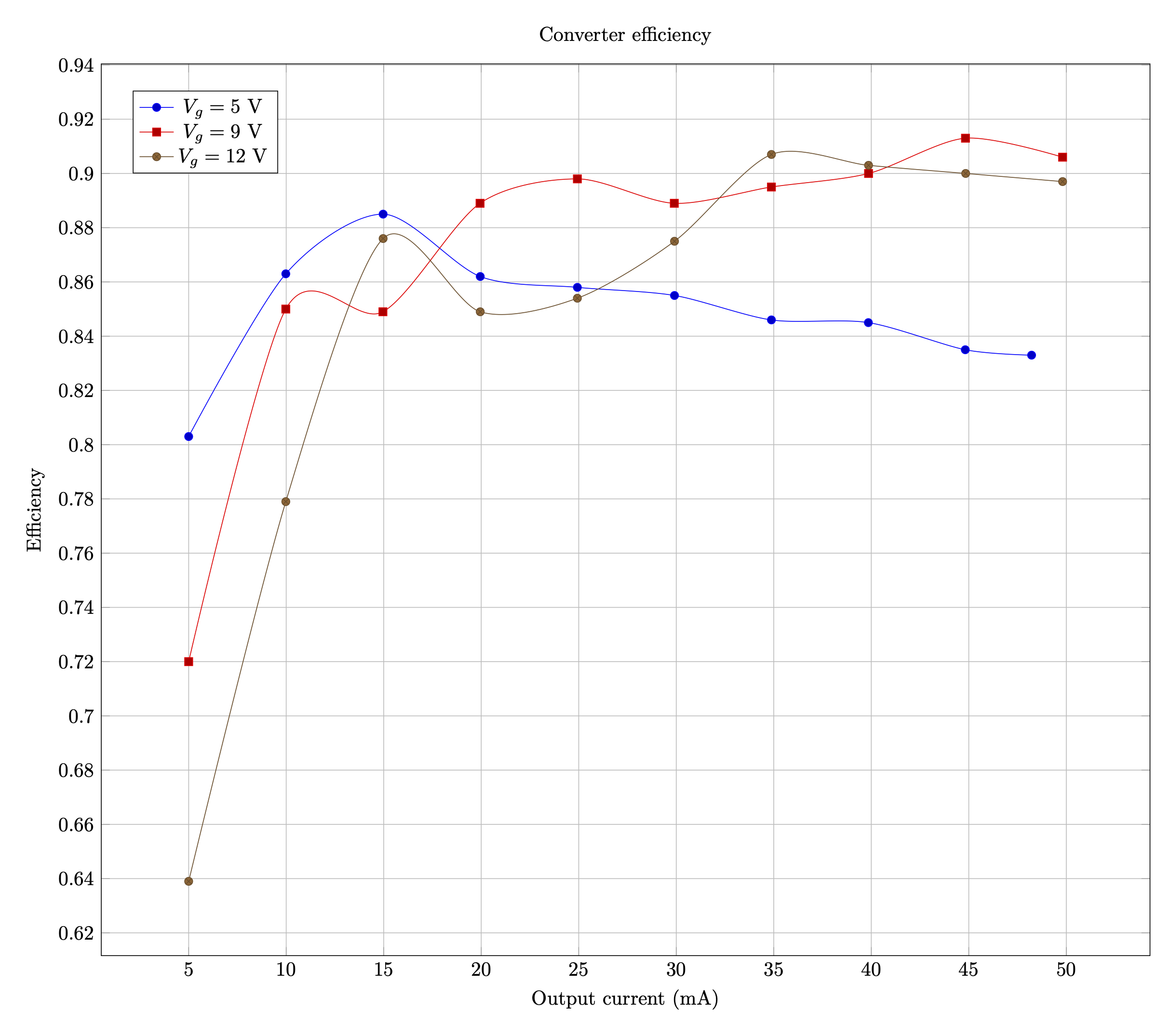
The efficiency measurements at 100 kHz switching frequency show a slight improvement over the previous experiment at 150 kHz. The converter is capable of nearly 90% efficiency over a wide range of conditions, peaking at over 91%. The end of the curve at 5 V shows that current limiting kicks in at Iout = 45 mA, as a precaution against saturating the transformer.
![]()
With that, and the end of April arriving, I think it's time to call it a wrap on this project. All of the characteristics of this flyback converter have been verified on the bench. Lastly, just to show it does in fact light Nixie tubes:
![]()
-
Finishing touches
05/03/2020 at 17:15 • 0 commentsI thought i called it a wrap on this project, but there were still a few small things to investigate. Here are the changes I made, which now puts things in a finished state.
Increase switching frequency to 120 kHz. At 100 kHz, the peak current on the transformer primary side would exceed its saturation rating (3 A). In DCM, the peak current is independent of the input voltage. Based on an load current of 30 mA, 120 kHz provides a better solution for keeping the primary-side current within datasheet limits.
Changes to current sense network: increase R_sense to 33 mΩ and remove R_SL (use a 0 Ω jumper). DCM is stable without an artificial ramp, but simulations showed the converter can drop into CCM for transients at low input voltage. Unfortunately, there is no combination of R_sense and R_SL that simultaneously limit the peak current to 3 A and guarantee stability in CCM at this low frequency, while respecting the 2 kΩ limit on R_SL. The biggest transient is at startup, and CCM operation can be prevented there with a generous soft-start time. Simulations showed effects on the load-step transients were tolerable, so I decided to use a R_sense, R_SL network that would solve for the peak current limit only. As a consequence, it's expected the output voltage will droop when the load current exceeds 30 mA as the LM5155 is limiting the current to protect the transformer core from saturating. The lower switching frequency also means a larger filter capacitor is possible, so C11 was increased to 22 nF.
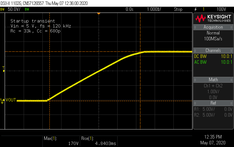
Increase soft-start capacitor to 47 nF. Simulations showed a longer startup time keeps the converter out of CCM during startup. This choice more than doubles the startup ramp time to about 5 ms.
![]()
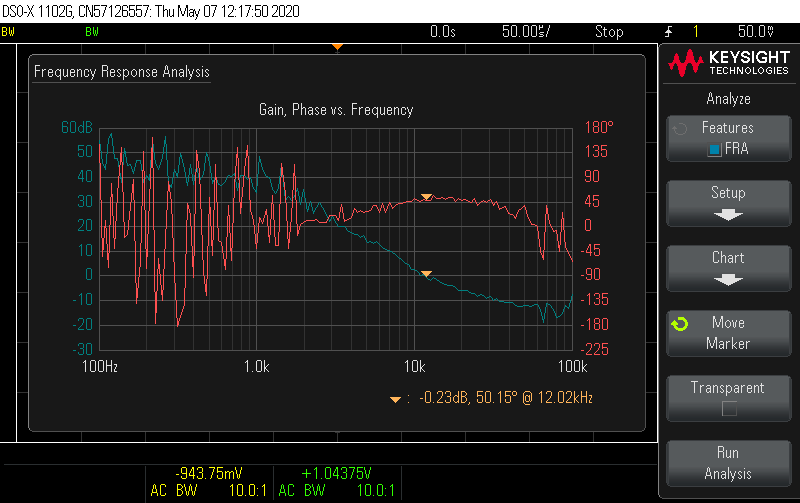
Improve compensation network. I derived an analytical small-signal model of the flyback in DCM-CPM, which informed better choices of the compensation network. I also made an error in the previous script and forgot to include the PWM gain factor (parenthetically referenced in tiny text on the LM5155 datasheet ... thanks TI). In DCM, the low-frequency behavior of the loop is approximately a single-pole system, with identical gain and pole frequency to a buck-boost controller. Without a RHP zero in the model, there is no obvious and natural choice for a HF pole, so I removed the second capacitor and used R = 33 kΩ and C = 680 pF to set the crossover at 12 kHz with 60° phase margin. These charts show the predicted and measured results. The converter now reacts to 5 mA load steps so fast, it wasn't even possible to capture them on the scope.
![]()
![]()
These changes deliver a small hit to the efficiency and limit the output current, but this is to be expected. The converter still achieves about 90% efficiency at high loads at 9V and 12 V input. Efficiency calculation were omitted after the converter hits the current limit.
![]()
Nixie Tube 170 V flyback DC-DC power converter
Design walkthrough and evaluation of a flyback converter from scratch