There are three key components in a calculator:
- Display, to show the results
- Microcontroller, to do all the calculus
- Keyboard, to input the values and operations
There are other components like voltage regulators, battery chargers, on/off circuits but this project is focused only in building a calculator, it doesn't need to be standalone.
The Display
Lets start with the display, it had to be able to show a reasonable number of digits plus the signs, decimal point and exponent of scientific notation. I considered using small 7 segment displays, but I couldn't get them because nobody in my area sold them, and I couldn't import them either. That's why i choose the nokia 5110 lcd display.
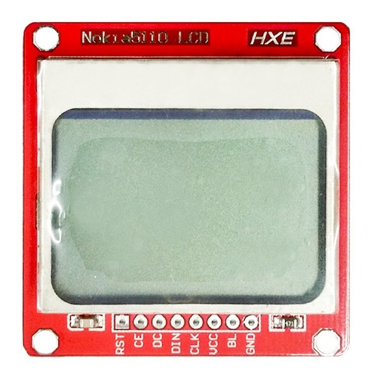
It has 48x84 pixels, and if we use 8x6 pixel characters we end up with a display of 6x14 characters. That's a good ammount of characters.
It uses a SPI compatible serial communication protocol. And with two more GPIO the microcontroller was able to configure parameters like contrast and send all the graphics data.
The Microcontroller
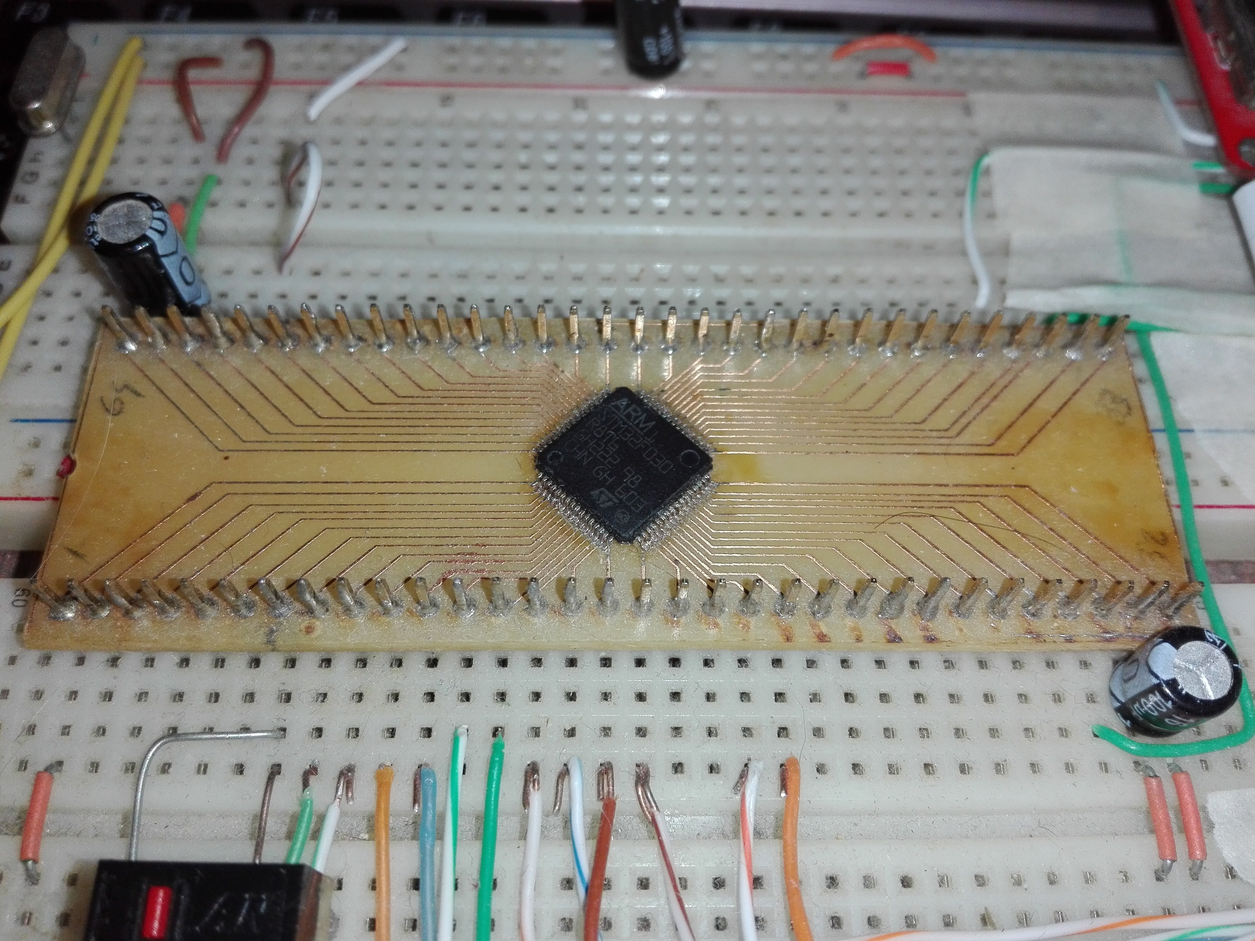
I used a stm32f030r8 as the main microcontroller. It's a simple ARM cortex-m0 with no floating point unit. It has 64K bytes of flash memory and 8K bytes of ram. But it also has other interesting features, like SPI, USART, Timers, and Direct Memory Access (DMA) that I used in the graphics and the matrix keyboard.
This micro comes in a LQFP-64 package. A pcb was made to adapt the smd pins to a "DIP" format.
The Keyboard
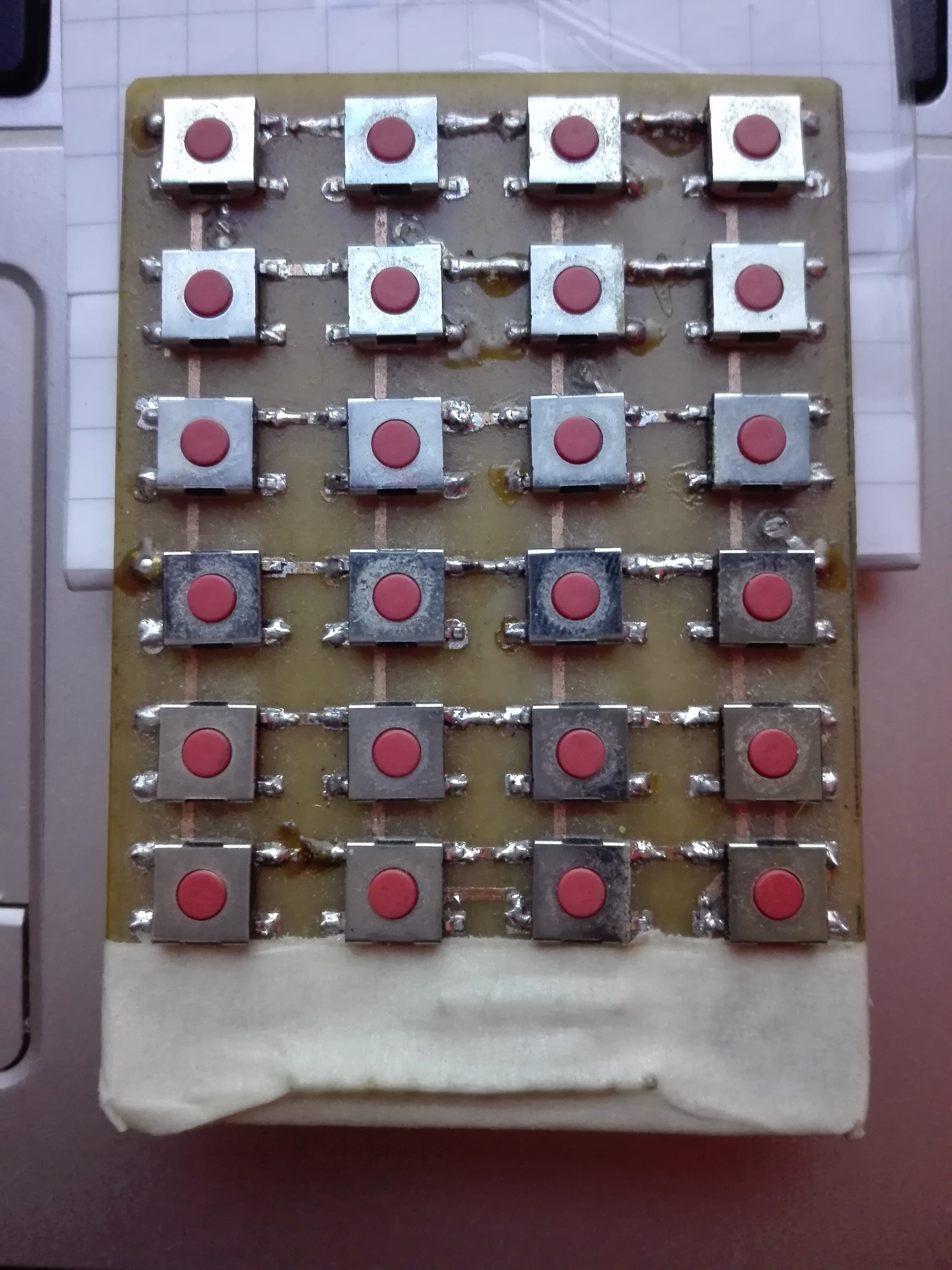
I made a 6x4 matrix keyboard for this calculator. The switch push button is 6x6mm and the pcb is 70x50mm.
I also made a layout with paper and transparent tape, to know the meaning of each key and avoid noise on the exposed copper traces.
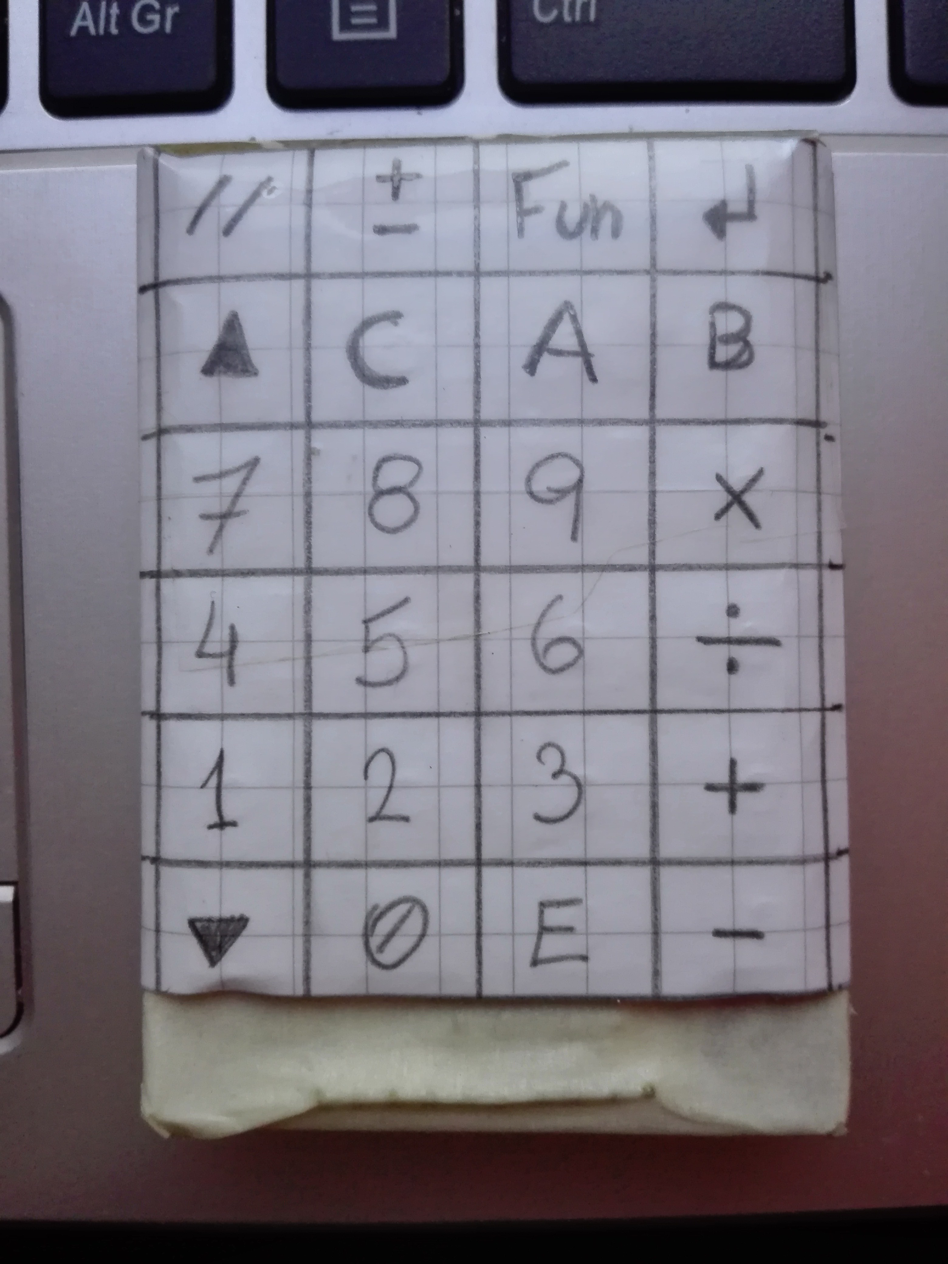
With the extra keys I added more functionalities like the '//' parallel (for impedance), '+-' change sign (unused), 'Fun' for functions and Enter. Only the parallel is implemented. In the key 'B' a inverse function was coded.
These are the main components used in the project. In the following logs I'm going to explain how all the pieces interact with each other and how the behavior was defined.
Discussions
Become a Hackaday.io Member
Create an account to leave a comment. Already have an account? Log In.