 Lars
LarsAs mentioned in a previous entry, the robot is using two revolution counters, one on each wheel. The encoders are not directly connected to the wheel, but to the motor drive rod. The drive rods are then immediately linked to the wheel.
The encoder have several purposes in this project. On the one hand they are used to monitor the wheel rotation. If the robot detects an object, depending on the scenario, a value is stored in the FPGA, which describes how far the vehicle should turn. Therefore, the encoders can be used to detect whether the "programmed" behavior has been applied and the preset angle of rotation has been reached. If this is the case, the robot can continue its journey.
The encoders can also be used to detect when the wheels are no longer turning, i.e. when the rotational speed is zero. If this is the case, the FPGA again compares the actual state with the target state of the wheels: If the wheels do not turn (actual state), but the state "driving" was stored (target state), an error has occurred. This error is usually caused by the robot getting stuck.
Future applications could be a sort of mapping system for measuring different rooms. The position of the robot can be determined by the number of wheel rotations.
The structure:
The revolution counter unit essentially consists of 2 components.
1. The magnet plate consists of 3d-printed PLA and contains 4 neodymium magnets each. They are arranged in 90 degree angles to each other. Please note that the south pole of the magnet is mounted towards the sensor, because the Hall sensor I use only detects positive magnetic fields.
2. Hall sensors are sensors whose output signal depends on the surrounding magnetic field. They therefore detect the magnetic fields and then change the electrical state of their output. In order to evaluate the output signal with the FPGA, the Hall sensor must be connected correctly. For the robot I use a unipolar Hall sensor of type H501. Unipolar in this case means that the sensor detects only the positive pole of a magnet. The output gets a high state when a positive magnetic field is applied and drops to GND when this field is no longer present.
Another important feature is the Schmitt trigger. This is a comparator circuit that converts a linear output signal into a square wave signal so that it can be read by the FPGA. It is important that the sensor has this circuit; otherwise it must be built externally.
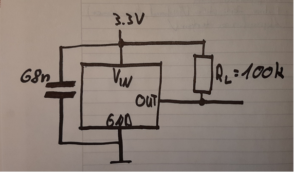
The sensor is powered by the 3.3V on-board power supply of the robot. The small foil plastic capacitor is used for interference suppression. The output signal requires a pull-up resistor with a value of 100k.
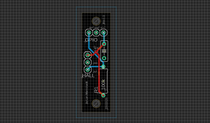
I then transferred this circuit to Eagle and ordered the circuit boards. The PCB fits well into the holder provided for it in the robot.
Behavior of the sensor:
State at output: Condition:
0 => no magnetic field
1 => Positive magnetic field
The note shows that the sensor can detect two states. If the sensor does not detect a magnetic field, a low level is present at the output. A high level only occurs if the south pole of a magnet is detected by the sensor. When the magnetic field is no longer present, the output falls back to low.
This behaviour can be easily seen on the following extract of an oscilloscope diagram. The square wave signal shows the output of the Hall sensor while the robot is moving:
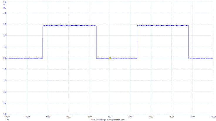
This diagram shows the voltage at the output of the hallsensor over time (ms). You can see the periodic square-wave signal that is generated by the consistent movement of the wheels.
Discussions
Become a Hackaday.io Member
Create an account to leave a comment. Already have an account? Log In.