 Evgeny
Demo of the result so far (don't mind my "technique"):
There are few different topics to cover, each can be interesting on it own.
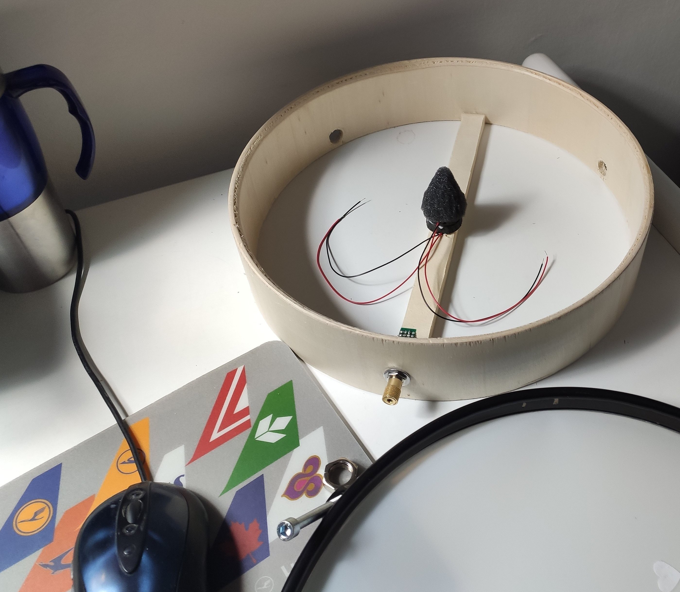
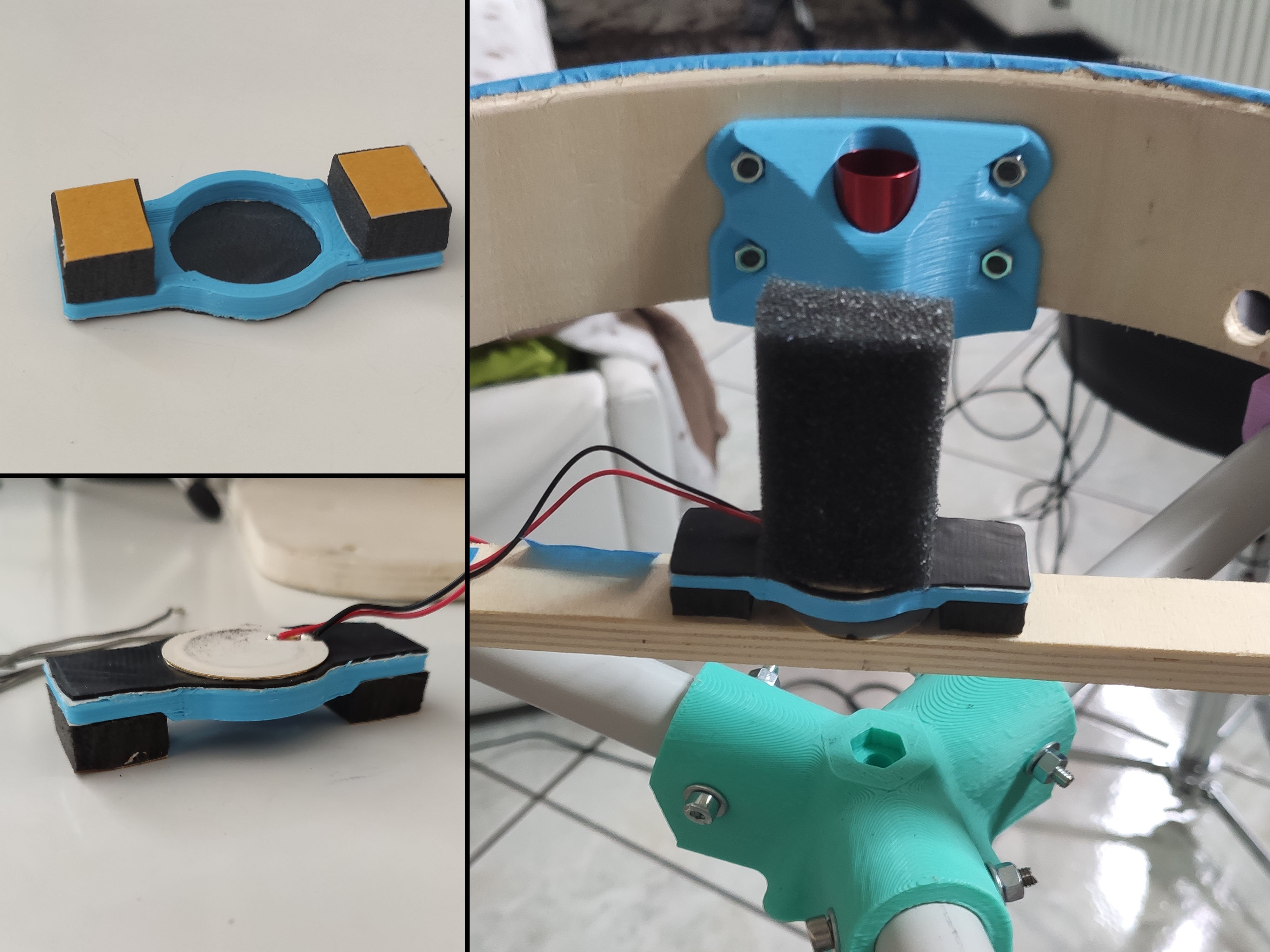
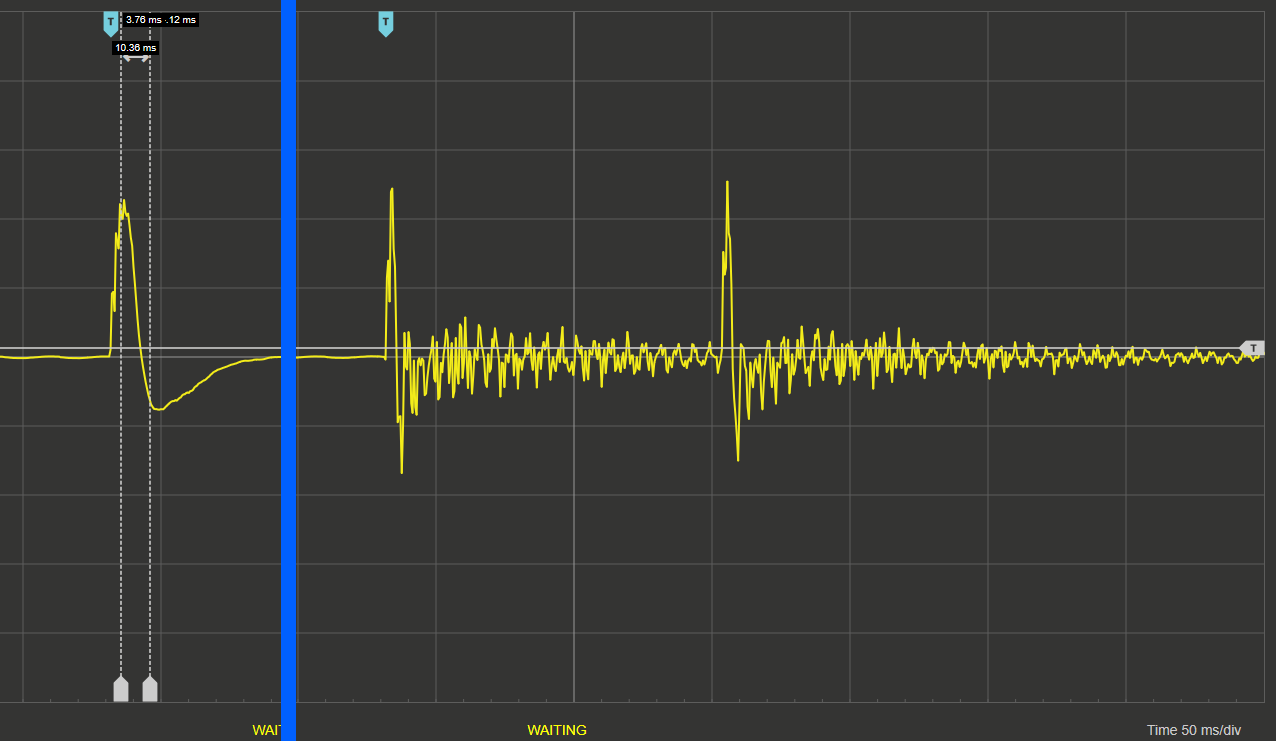
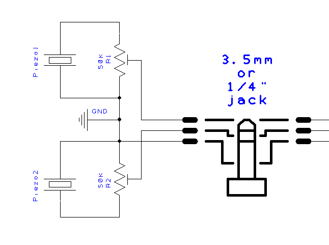
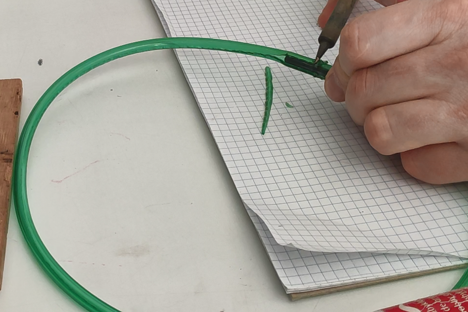
- diy piezo trigger
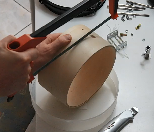
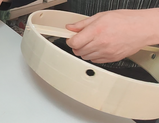
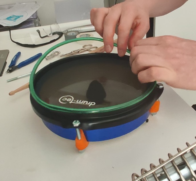
- making custom mesh pads
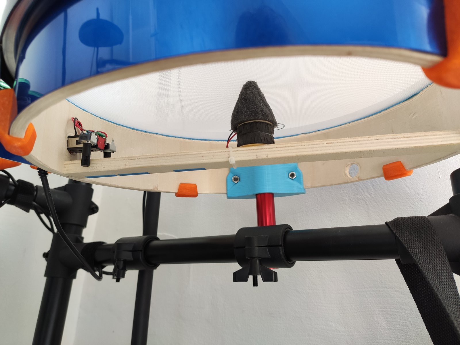
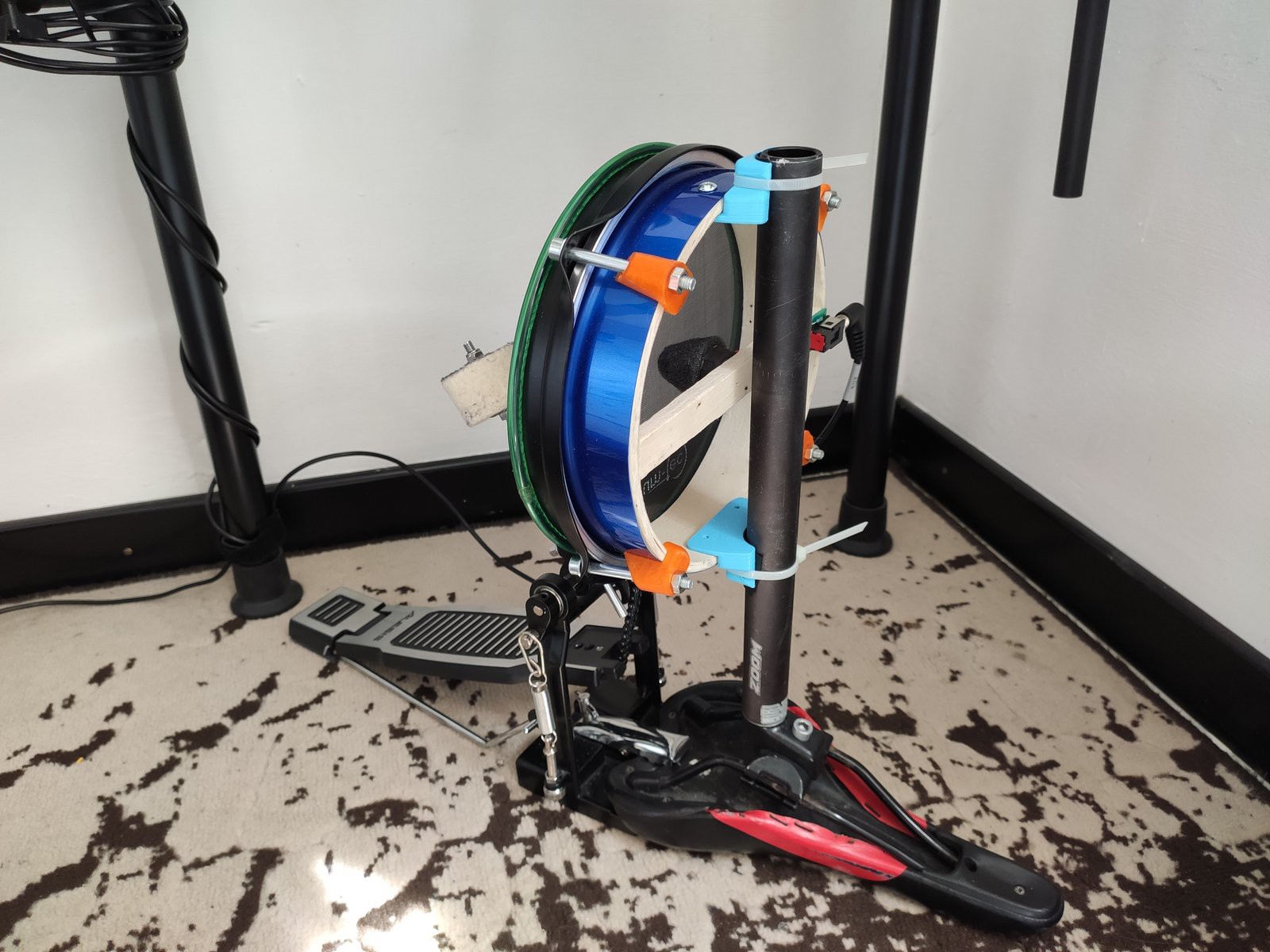
- making kick pad (using one mesh from #1)
- "adjusting" DM6 electronics.
- things I have tried and decided to move on.
For each there is going to be a full set of instructions, in case one decides to follow the road.
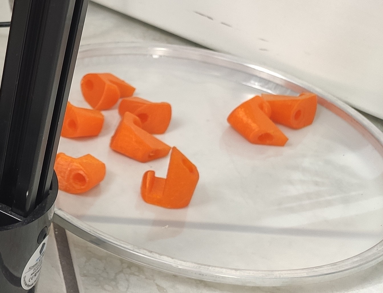
3D printed components can be found here: https://www.thingiverse.com/thing:4296480
The following illustration summarizes* it all pretty well:
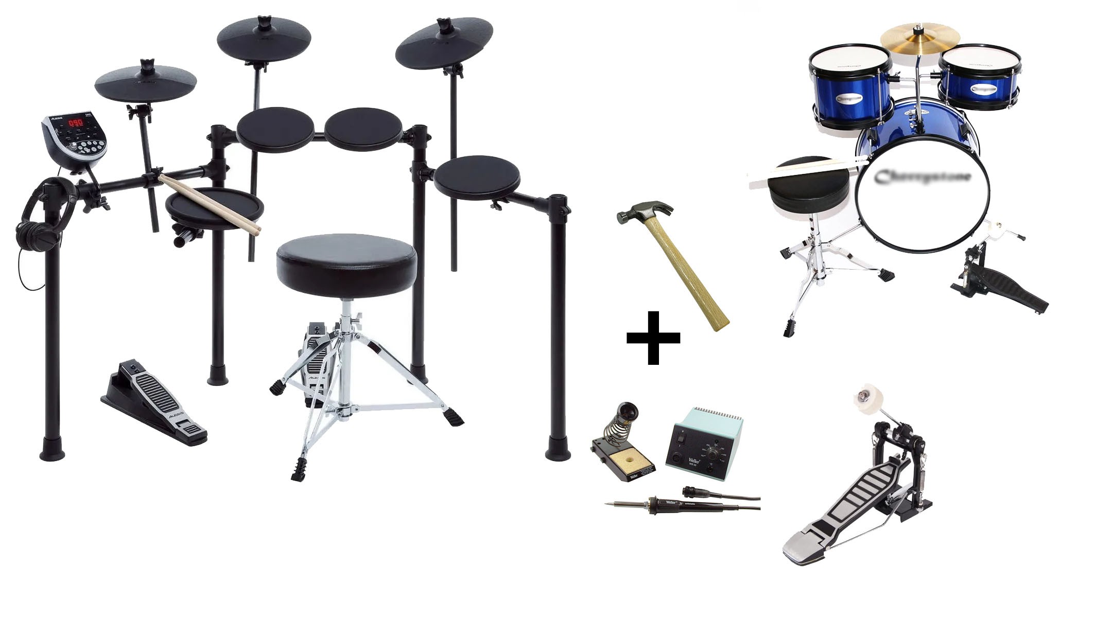
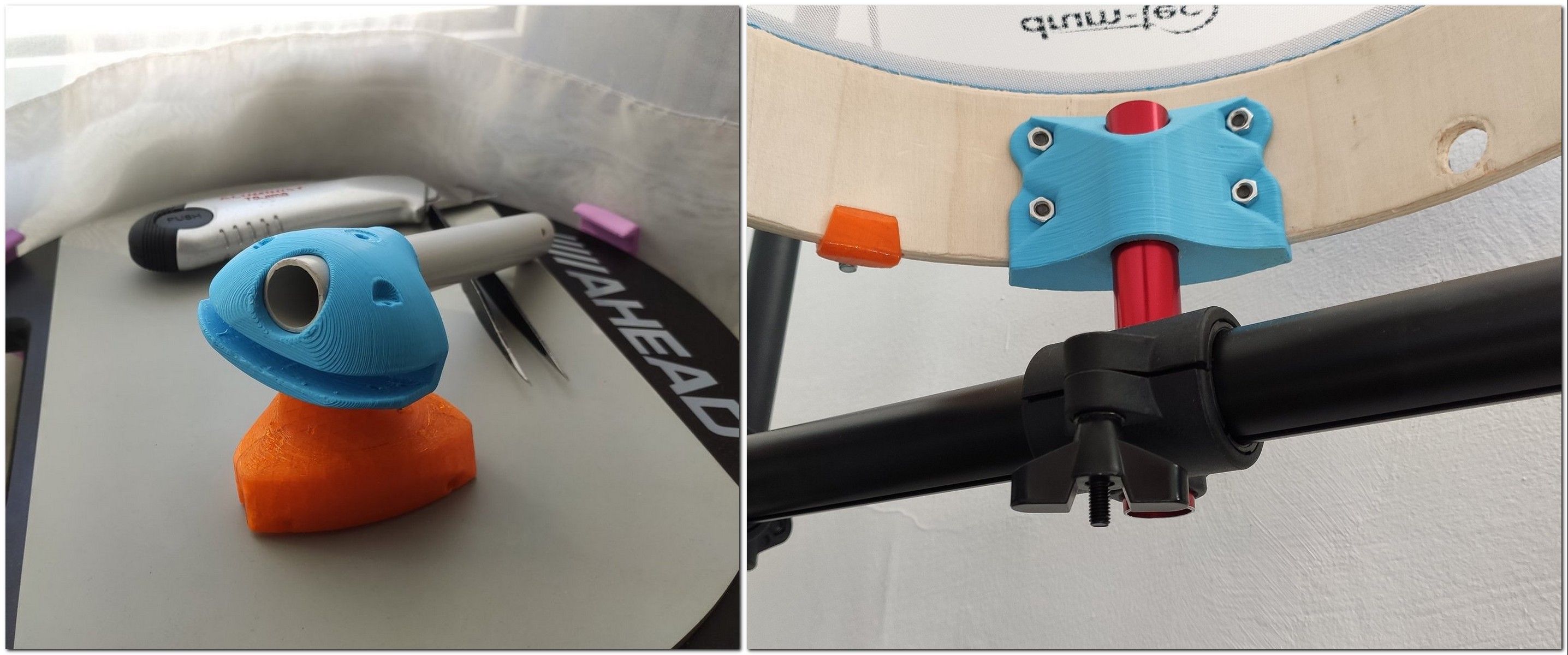
* basic cheap drum module was 'improved' by converting it to mesh.
The drum head are based on toy drum kit with 2x8" and 1x12" 'drums'.
To make them work with original drum module it needed some hardware 'adjustments'.


 benw
benw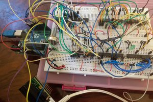
 Matt Bradshaw
 marcin
Similarly, I need to know the value of L26. It's an inductor on the I/O daughterboard. I could desolder L25, which is adjacent, but it'd sure be nice if there was a schematic available.